The Keep and No Keep modes can be activated via the Keep Mode and No Keep Mode icons in the Tools toolbar.
For more information, see Installation & Deployment User's guide: Common Installation and Administration Tools: Managing Settings: About Settings.
Keep Mode
This mode is identical for both geometrical set and ordered geometrical set environments, whatever type of the input and output (= result) elements are, that is to say whether they are datum or not.
The input element:
- remains in the show area
- can be detected and selected in the 3D geometry
- can be detected in the specification tree
Let's take an example with the Split command:
-
Check that Keep Mode
 is activated.
 -
Click Split
 .
. -
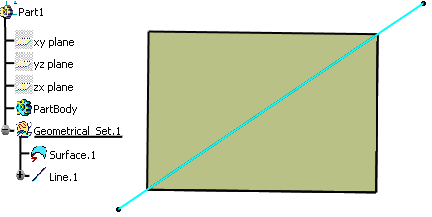
Split the surface by the line.
The whole surface remains in the show area. 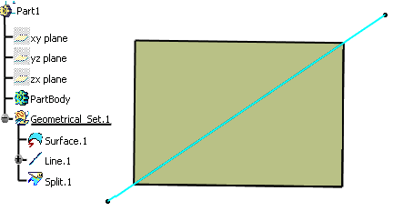
No Keep Mode
Here is the list of modification commands:
Command
Conditions
All transformations Creation/modification mode Blend With Trim support Bump Connect Curve With Trim mode Corner With Trim mode Curve Smooth Diabolo No GSD plane as input Extrapolate With Assemble result Fillet With Trim Support Healing Inverse Join Near Shape Morphing Split No GSD plane as input Sweep Tangent sweep with Trim mode Trim Wrap Curve Wrap Surface
Command
Conditions
3D Curve Offset All transformations Creation/modification mode Combine Develop Offset Parallel Curve Project Variable Offset
This mode transforms contextual creation features into modification features.
Datum Input and Datum Result
- is deleted
- is replaced by the created feature (if their dimensions are strictly identical)
- its child features are impacted
=> Behavior 1 (see table below)
Let's take an example with the Split command.
-
Check that No Keep Mode
 and Create Datum
 are activated.
 -
Click Split
 .
. -
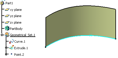
Split the curve by the point.
The input curve is replaced by the resulting split curve and the surface is impacted. 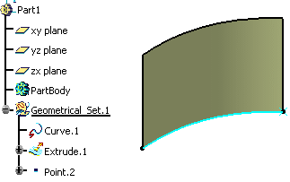
Feature Input and Datum Result
-
Geometrical set environment
- is put in the no show area
- cannot be detected and selected in the 3D geometry
- can be detected and selected in the specification tree
- its child features are not impacted
=> Behavior 2 (see table below)
Let's take an example with the Project command.
-
Check that No Keep Mode
 is activated.
 -
Click Project
 .
.
-
Click Create Datum
 .
. -
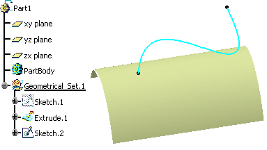
Project the element (Sketch.2) onto the surface (Extrude.1)
The input sketch is put in no show and a datum curve is created. 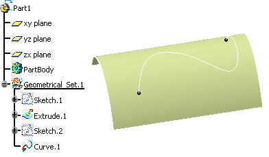
-
Ordered geometrical set environment
- is put in the no show area
- cannot be detected and selected in the 3D geometry
- can be detected and selected in the specification tree
- its child features are impacted if the created feature is inserted before them
Let's take an example with the Split command.
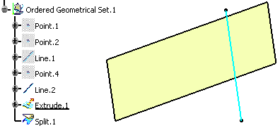
The extruded surface has a child feature (Split.1) and is defined as the current object.
-
Check that No Keep Mode
 is activated.
 -
Click Split
 .
.
-
Click Create Datum
 .
. -
Split the extruded surface with the line.
The extruded surface is put in no show and its child feature is impacted: its input is now the new surface (Surface.1). 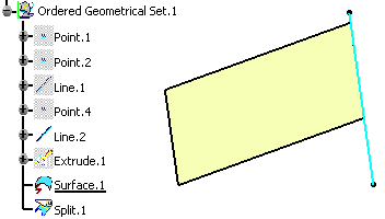
Datum or Feature Input and Feature Result
-
Geometrical set environment
=> Behavior 2 (see table below)
-
Ordered geometrical set environment
- is in the ghost area
- cannot be detected and selected in the 3D geometry
- can be detected and selected in the specification tree
- its child features are impacted if the new feature is the created inserted before them
=> Behavior 3 (see table below)
Let's take an example with the Offset command.
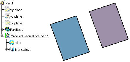
The fill is defined as the current object.
-
Check that No Keep Mode
 is activated.
 -
Click Offset
 and offset Fill.1.
The offset surface is created before the translate. The fill is absorbed and the translate is impacted. 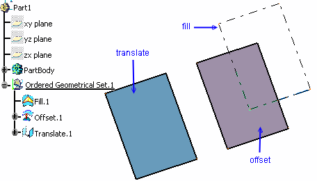
Datum Result Feature Result Datum Input Geometrical Set Behavior 1 Behavior 2 Ordered Geometrical Set Behavior 1 Behavior 3 Feature Input Geometrical Set Behavior 2 Behavior 2 Ordered Geometrical Set Behavior 2 Behavior 3
- The default option is Keep mode for creation features and, and No Keep mode for modification features.
- Features created using the contextual menu are always set to Keep mode.
- If a sub-element is selected as an input of a command in No Keep mode, it is not put in the no show area.
- When editing a feature, you cannot change its mode.
![]()

