The file of vectors to filter is DeformationVectors01.txt in the samples directory.
-
Click Vectors Field Filter
 .
.
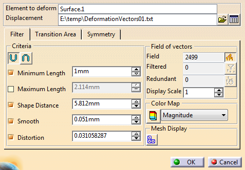
The Vectors Field Filter dialog box is displayed: -
Select the Element to deform.
and click to select a Displacement (in our example,
DeformationVectors01.txt in the samples directory).
to select a Displacement (in our example,
DeformationVectors01.txt in the samples directory).The Element to deform can be: - A surface
- A mesh (Field Limit is not supported).
- A displacement definition file,
- A Deviation Analysis feature (e.g. created with Quick Surface Reconstruction),
- A DSMVectors feature created with the Displacement Optimization command.
-
If necessary, click
 to:
to:- Display the list of files selected,
- Reset your selection,
- Remove files from the selection.
-
In the Filter tab, define a filter:
-
Under Criteria, the checkboxes are populated
with default values computed from the input. You can modify
these values, within an allowed range. A message is
displayed when you enter invalid values.
Select the checkboxes to combine the different criteria you want to use, and define their values:- Minimum Length: discards vectors with a length smaller than the value you define.
- Maximum Length: discards vectors with a length higher than the value you define.
- Shape Distance: discards the vectors with a distance between their origin point and the Element to deform higher than the distance you define.
- Smooth: computes the difference between the length of the vector and the average length of all the vectors. If this difference exceeds the value you define, the vector is discarded.
- Distortion: discards the couples of vectors with a distortion exceeding the value you define.
-
Then click either:
-
 :
The resulting filter is the union of the selected
criteria,
:
The resulting filter is the union of the selected
criteria, -
 :
The resulting filter is the intersection of the selected
criteria.
:
The resulting filter is the intersection of the selected
criteria.
-
The result of the filter is displayed under Field of vectors:
- Field: Displays the number of the vectors of the field,
- Filtered: Displays the number of the vectors filtered.
- Redundant: Displays the number of redundant vectors.
Still under Field of vectors, click:
-
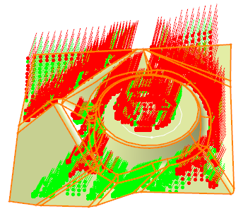
 :
Displays the vectors of the field,
:
Displays the vectors of the field, -
 :
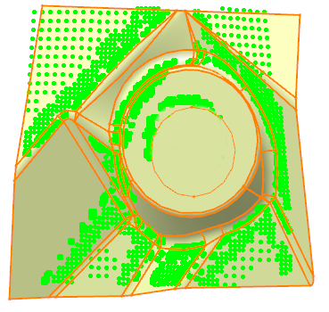
Displays the filtered vectors,
:
Displays the filtered vectors, -
 :
Displays the redundant vectors.
:
Displays the redundant vectors.
and define a scale to display those vectors.
-
Under Criteria, the checkboxes are populated
with default values computed from the input. You can modify
these values, within an allowed range. A message is
displayed when you enter invalid values.
-
Under Color Map, select the criterion for which you want to display a color map

and click .
.
The color map is displayed. It takes all the vectors of the field into account.

-
Under Mesh Display, click
 .
.
The mesh based on the target points of the field is displayed. -
Go to the Transition Area tab
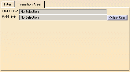
to select a Limit Curve and/or a Field Curve.
An arrow indicates the direction in which the area is created. Click Other Side to invert that direction.
The Limit Curve is described in using a Limit Curve.
The Field Limit defines an area where you want to remove vectors, e.g. below, the circle has been selected as a Field Limit, with its direction pointing inwards:
-
Click OK. The filtered vectors are cleaned.
A DSMFilter datum is created. It is editable, and can be used as a clean substitute of the Displacement selected in step 2.
![]()