You will:
- Select the original shape,
- Apply a displacement defined by a cluster of vectors
(these vectors have been computed by a dedicated action).
The original shape is thus transformed into a new one, by a digitized morphing.
The displacement is defined by a vector file. It is a text file that:
- Contains one point and one vector per line (X, Y, Z, DX, DY, DZ).
- Contains only coordinates, no comment line, no title.
- The decimal separator used in this text file must be that defined in your OS regional settings.
-
Extract of a text file:
You can also define the displacement by selecting a CATAnalysis or a Deviation Analysis feature.
- The resulting surface is strongly dependent on the deformation field
...
Be careful to use a consistent field of vectors (with the right format such as X Y Z without separator). - To ensure a high accuracy of the output, the source points must be close to the surface to deform.
- Depending on the number of faces of the element to deform,
of the number of vectors and of the complexity of the morphing, the computation may be time consuming.
The morphing is computed at each point found in the text
file, with the corresponding vector,
resulting in a new, deformed shape.
Using a Deviation Analysis Feature - Limitations
A Deviation Analysis feature is not a representation of a deformation of
a shape. It is only a set of vectors resulting of a deviation analysis
computation between a cloud of points and a surface: the displacements
created by a Deviation Analysis between two shapes are different from the
displacements to apply to transform a shape into the other one, especially
in the case where the initial shape presents sharp edges or curvature
variations or when the deformation includes a "stretching" of the initial
shape.
Examples:
Deviation Analysis vectors between Shape 1 and Shape 2:
Displacements required to transform Shape 1 into Shape 2:
Deviation Analysis vectors between Shape 1 and Shape 2
Displacements required to transform Shape 1 into Shape 2
Deviation Analysis vectors between Shape 1 and Shape 2
Displacements required to transform Shape 1 into Shape 2
You can use the
Displacement Optimization command to optimize
vectors from a Deviation Analysis.
The file of vectors used to compute the deformation is DeformationVectors01.txt in the samples directory.
The sample is a simple example.
The next task explains how to use a limiting contour.
-
For a better understanding of the field of vectors (and eventually find data inconsistencies),
you may wish to use the option
Display all elements using Z-buffer depth in Tools > Options > Display > Visualization. -
Click the Digitized Morphing icon
 .
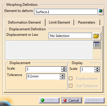
The Digitized Morphing dialog box is displayed:
.
The Digitized Morphing dialog box is displayed:
before clicking the Digitized Morphing icon
The dialog box looks like this:
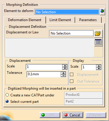
You can create the result in a new CATPart that will be inserted under
the Product you are working in,
or in the current CATPart, that is the one you have activated.
Select the requested option.
The names of the CATPart or of the product are given for information only
and cannot be edited.
-
Select Surface.1 as the Element to deform.
This is the original shape. It can be a solid, a surface, or a curve and its support surface.
you can select one or several elements
If you are not working with a limit curve, click to select several elements.
If you select one element, its name is displayed in the text field.
If you select several elements, the information given is the number of elements selected. -
Select the deformation element. It can be:
-
A CATAnalysis to define the displacement (the text file is generated automatically):
- Place your cursor in the Displacement field and select a CATAnalysis,
- The Displacement Definition File dialog box is
displayed:
- Eventually select a directory where you want to save the text file you
are generating.
Enter the name of the text file in the File name field and press Save. - The Displacement Definition File dialog box vanishes.
The text file with the points and vectors is generated in the directory you have selected,
and the name of the text file is displayed in the Displacement field of the Digitized Morphing dialog box.
- A Deviation Analysis.x feature (created with Quick Surface Reconstruction). The dialog box is updated automatically.
- A DSMVectors.x feature created with the Displacement Optimization command.
- A deformation law.
- One or several vector files:
- Click
 and select
the vector files. We have selected
DeformationVectors01.txt from the samples directory.
and select
the vector files. We have selected
DeformationVectors01.txt from the samples directory.
- Click
-
-
Optional: Click
 to:
to:- Display the list of selected files,
- Reset your selection,
- Remove files from the selection.
-
Optional: Tune up the displacement and display paramaters:
- The displacement
Scale
applies a coefficient on the vector to increase or reduce the
displacement.
If you enter a negative scale, the displacement is computed in the opposite direction. The displacement Tolerance can be represented by a sphere centered on each ideal deformed point.
If the actual computed point is not within the tolerance sphere, as shown in the red circle, it is ignored.
-
The display Scale applies a coefficient on the vectors to increase or reduce their display length.
-
When selected, Displacement displays the vectors:
- The original points are displayed in blue,
- The output points are displayed in red,
- The vectors are displayed in green.
- After a preview, and when selected,
Out Tolerance
displays the points that do not meet the tolerance as follows:
- The displacement
Scale
applies a coefficient on the vector to increase or reduce the
displacement.
-
Click Preview after each modification to see its impact.
- The morphing is computed, and the deformed shape is displayed in blue.
- The number of points taken into account for the computation may be less than the number of input points, and will not exceed 30000.
- Even if you process less than 30000 points, the number of remaining points (i.e. the number of points taken into account for the computation) can be less than the number of input points, due to an optimizing process.
- The dialog box is updated automatically. Statistics on the computation are displayed. They pile up as you modify the parameters (the picture above is an example, and the statistics may vary as the computation goes on).
-
Click OK. A deformed shape is created and a DigitizedMorphing.1 feature is created in the specification tree.
The input is sent to the NoShow.
- If you have selected several elements to deform, one feature is created for each element to deform.
- If the feature to
deform is a surface or curve, the deformed
feature is created as DigitizedMorphing.x into the in work geometrical set.
The input is sent to the NoShow.
If the feature to deform is a solid, the deformed feature is created as DigitizedMorphingSolid.x inside the body containing the selected solid. - If the element to deform was a curve lying on a surface, the resulting curve does not lie on the resulting surface.
- A link is created with the displacement
file.
This link can be checked and updated with the Update Digitized Morphing command.
![]()