when using a displacement map to alter a die face development, you may have to limit the change to take place within the punch opening outline. As the displacement map encompasses a larger area, a Limit Curve to control what portion of the die face will be altered.
The file of vectors used to compute the deformation is DeformationVectors01.txt in the samples directory.
Please refer to Digitized Morphing for more information on the general operating mode.
-
Click Digitized Morphing
 .
The Digitized Morphing dialog box is displayed.
.
The Digitized Morphing dialog box is displayed.
-
Select Surface.1 as the Element to deform.
-
In the Deformation Element tab, click
 and select
DeformationVectors01.txt from the samples directory.
and select
DeformationVectors01.txt from the samples directory.
-
Go to the Limit Element tab and select Sketch.1 as the Limit Curve.
You can select only one curve, open or closed, as the Limit Curve.
It must lie on the surface to deform, and divide this surface in two distinct sides.
If you select a Limit Curve, you can process only one element to deform.
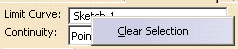
The name of the Limit Curve is displayed in the Limit Element tab.
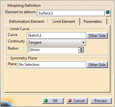
A contextual menu is available to clear the selection.
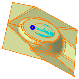
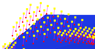
Once the Element to deform and the Limit Curve are selected, the area to deform is highlighted.
-
Optional: Click Other Side to process the area located on the other side of the Limit Curve.
The highlight is updated accordingly. -
Define the type of Continuity between the output surface and the Limit Curve (Point or Tangent).
-
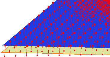
Define the Radius of a virtual circular pipe centered on the limit curve, within which points are removed.
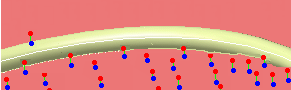
This radius is visualized as a dark blue sphere (we set it to 2).
-
Optional: Go to the Parameters tab.
-
Click Preview.
It can be time consuming.
If the displacement implies a large distortion on the shape, a message is displayed and the corresponding vectors are highlighted.
-
Click OK when you are done.
![]()