Locating instances consists in specifying anchor points. These points are created in the Sketcher.
You can also find information about patterns and updates by reading Optimizing Part Design Application, Patterns.
-
Select the feature you want to be patterned.
Note that whenever you are using a feature list, you need to multi-select the features in the order they were created.With 3D Points With Axis Systems 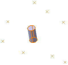
-
Click User Pattern
 .
.
The User Pattern Definition dialog box appears.- If you click the User Pattern
prior to selecting any geometry, by default, the object to
be patterned is the current solid. For more information,
refer to
Patterning Current Solids.
- If you change your mind and decide to
pattern the current solid,
right-click the Object field and select Get
current solid.
If you want to create patterns of multiple elements, press Ctrl, select the required elements from the specification tree, and then click User Pattern.
The number of selected elements appears in the Object
box.

- You can also click the object to pattern bag
 beside the Object box, and then select the required
elements from the specification tree. The selected elements
appear in the list and the number of elements appears in the
Object
box.
beside the Object box, and then select the required
elements from the specification tree. The selected elements
appear in the list and the number of elements appears in the
Object
box. - You can create Part Design features, such as pads, pockets, shafts, grooves, and holes, on the fly while creating a pattern. To do so, right-click the Object box and select the required command.
- You can also click the object to pattern bag
- Checking the Keep
specifications
option creates instances with the limit Up to Next
(Up to Last, Up to Plane or Up to
Surface) defined for the original feature.

The Keep specifications option is not available while Patterning patterns.
- If you click the User Pattern
-
In the Instances section, define the Positions to pattern.
To define the positions you can:
The number of instances appears in the Number box.- Click
to select any point, axis system, repeated axis systems,
sketch, geometrical set, or ordered geometrical set from
the 3D area.
- Only points and axis systems are considered under geometrical sets, and ordered geometrical sets.
- If points, axis systems, geometrical set, or ordered geometrical set are already added to the Position Elements bag then the further addition of a geometrical set or an ordered geometrical set results in the removal of all the previously added elements in the bag.
- Only one ordered geometrical set or ordered geometrical set can be added in the Position Elements bag.
- If a point or an axis system is added or removed from the geometrical set or the ordered geometrical set used for defining the position of the pattern, a new instance is added or removed from the pattern at the location of the newly added or removed element.
- You can use trap select in the 3D area.
- Right click the Positions
box and select the required among following:
- Create Sketch: to create a new sketch with positioning points.
- Create Point: to create a point.
- Create Axis System: to create an axis system.
- Create Axis System Repetition: to create required number of axis systems, along with the defined curve, normal to the surface. See Create Multiple Axis Systems.
- If you select any of these elements, the corresponding icon is shown next to the Positions box. You can click the icon to edit the selected elements.
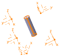
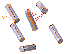
If you select an axis system to define the position, a red axis representation appears at the center of gravity of the object to pattern, or at an anchor.
- Click
-
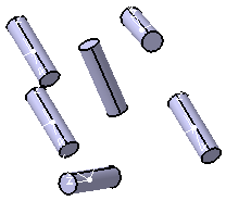
Click Preview.
The preview shows the instances at the defined position.
With 3D Points With Axis Systems 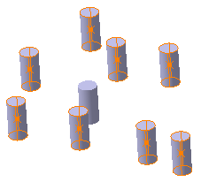
-
In the Objects to Pattern, select Anchor.
The application positions each instance with respect to its own center of gravity or the element to be duplicated. To change the position, click in the Anchor box and select a point, or an axis system.The contextual commands for creating the anchors are available from the Anchor box: - Create Point: for more information, see Creating Points
- Create Midpoint: creates the midpoint of the line you select
- Create Endpoint: creates the endpoint of the line you select
- Create Intersection: see Creating Intersections
- Create Projection: see Creating Projections
- Create Extremum
- Create Axis System
- Create Extract
If you create any of these elements, the application then displays the corresponding icon next to the Anchor box. Click the icon to edit the element.
-
Click OK.
Instances are created and UserPattern.x node is added to the specification tree.
With 3D Points With Axis Systems 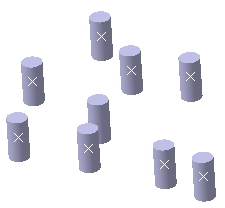
Editing a List of Features
Editing a list of features consists in adding or removing features from
the list. To do so, click the object to pattern bag
![]() beside the Object field and select the feature of interest
from the specification tree to add it to the list of features. To remove
a feature, select it from the list and click
Remove.
beside the Object field and select the feature of interest
from the specification tree to add it to the list of features. To remove
a feature, select it from the list and click
Remove.
Exploding Patterns
During your design, you may need to rework instances specifically. You will then have to use the Explode contextual menu item to delete your pattern while keeping geometry. For more information, refer to Exploding Patterns.
Note: The application does not allow you to cut, nor copy user patterns.
Create Multiple Axis Systems
-
In the User Pattern Definition dialog box, right-click the Positions box and select Create Axis System Repetition.
The Points Repetition dialog box appears. -
In the Type box, select the desired repetition type.
- If you select Clones, you need to specify the reference axis system for cloning. The specified axis system is cloned on all the repeated points.
- If you select Along Surface, you need to select a surface. The axis systems are created with point on the curve as origin, line tangent to the curve as x-axis, and line normal to the surface as y-axis.
-
Click OK.
The axis systems are generated based on the inputs.
Patterning Bodies
The application patterns the body's geometry without taking into account
the body's polarity. However, if then you insert the pattern obtained in
another body, then the application takes the polarity of this body into
account. This explains why patterned bodies are not visible if they are
inserted in negative bodies.
In the following example, the user pattern points to Body.2 included in
Body.3 which is a positive body. In this case, the pattern is visible in
the geometry area because the pattern's result is added to existing
geometry.
If Body.3 is changed into a negative body (the Add
feature was changed into a Remove feature), then the user pattern is no
longer visible because the pattern's result is subtracted from existing
geometry.