You can intersect:
- wireframe elements
- solid elements
- surfaces
Open the Intersection1.CATPart document.
-
Click Intersection
 .
. -
Select the two elements to be intersected.
-
Choose the type of intersection to be displayed.
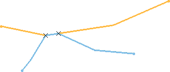
- a Curve (when intersecting two curves):
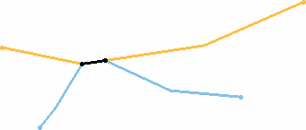
- Points (when intersecting two curves):
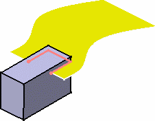
- a Contour: when intersecting a solid element with a surface :
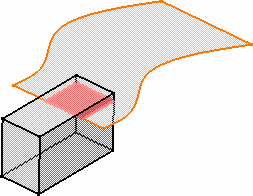
- a Face: when intersecting a solid element with a surface (we increased the transparency degree on the pad and surface):
-
Click OK to create the intersection element.
This element (identified as Intersect.xxx) is added to the specification tree. 
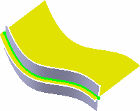
The above example shows the line resulting
from the intersection of a plane and a surfaceThe above example shows the curve resulting
from the intersection of two surfaces
Additional Parameters
Several options can be defined to improve the preciseness of the intersection.
Open the
Intersection2.CATPart document.Extrapolation
Options
These options are only available for surface-surface
intersections.
You can extrapolate the intersection result.
- If the Extrapolate intersection on check box is cleared,
the surfaces are intersected without extrapolation.
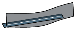
- If the Extrapolate intersection on check box is selected,
the surfaces are intersected with extrapolation. The results are as
follows:
If the first element option is selected. 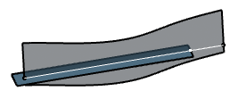
If the second element option is selected 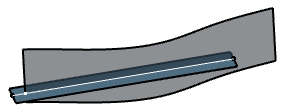
If the both element option is selected 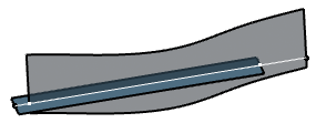
- Intersect non coplanar line segments
enables to perform an intersection on two non-intersecting lines.
When selecting this option, both Extend linear supports for intersection options are selected too. 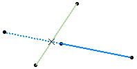
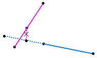
Intersection between the light green line and the blue line: the intersection point is calculated after the blue line is extrapolated Intersection between the pink line and the blue line: the intersection is calculated as the mid-point of minimum distance between the two lines
The following capabilities are available: Stacking Commands and Selecting Using Multi-Output.
- If you select a body or a hybrid body containing both solid and wireframe elements as input, only the solid elements are taken into account to compute the intersection.
- Avoid using input elements which are tangent to each other since this may result in geometric instabilities in the tangency zone.
- If the intersection stops at an edge and providing the edge can be merged with the intersecting element (if the distance is less than 0.1mm), then it is projected onto the intersecting element. The projection is integrated to the intersection result.
- Double-click the multi-output feature in the specification tree.
The Intersection Definition dialog box appears. - Select the Regenerate all deleted features
check box.

- The Regenerate all deleted features check box appears whenever the multi-output feature has fewer children compared to the result of number of features in the First Element box multiplied by the number of features in the Second Element box. If there are no additional intersections, selecting the Regenerate all deleted features check box will not change the number of children.
- Depending on your part, even if the above condition is fulfilled, new intersection outputs are generated only if they were present in the design before.
- Optional: Click
Preview.
All intersection features are displayed in the work area. In the specification tree view, they are aggregated under the multi-output node. 
The outputs are inserted after the last element in the node and are numbered accordingly, instead of being inserted at their original positions. - Click OK.
The intersection outputs are regenerated. 
You can undo the regeneration operation to go back to the previous design stage.
![]()