The application allows you to define three types of patterns:
- Rectangular Patterns
- Circular Patterns
- User patterns
This document deals with the following:
-
How to create a rectangular pattern (step-by-step scenario)
You can also find information about patterns and updates by reading Optimizing Part Design Application, Patterns.
-
Select the feature you wish to copy, that is the pocket as shown:
-
Click the Rectangular Pattern icon
 .
.
The Rectangular Pattern Definition dialog box that appears displays the name of the geometry to pattern.
If you click the Rectangular Pattern icon
prior to selecting any geometry, by default, the object to be patterned
is the current solid. For more information, refer to
Patterning Current Solids. 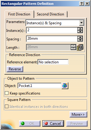
If you change your mind and decide to pattern the current solid, click the Object field and use the Get current solid contextual command.
If you want to create patterns of multiple elements, press Ctrl, select the required elements from the specification tree, and then click Rectangular Pattern....
The number of selected elements appears in the Object box.Each tab is dedicated to a direction you will use to define the location of the duplicated feature. In this task, you will first set your specifications for the first direction.
Reference Direction
-
Click the Reference element field and select the edge as shown below to specify the first direction of creation.
An arrow is displayed on the pad. If needed, click the Reverse button or click the arrow to modify the direction.
- To define a direction, you can select an edge or a planar face.
- Contextual commands creating the reference
elements you need are available from the Reference element
field:
- Create Line: For more information, see Creating Lines.
- X Axis: the X axis of the current coordinate system origin (0,0,0) becomes the direction.
- Y Axis: the Y axis of the current coordinate system origin (0,0,0) becomes the direction.
- Z Axis: the Z axis of the current coordinate system origin (0,0,0) becomes the direction.
- Create Plane: see Creating Planes.
If you create any of these elements, the application then displays the corresponding icon next to the Reference element field. Clicking this icon enables you to edit the element.
-
Let the Instances & Spacing options to define the parameters you wish to specify.
The parameters you can choose are:- Instances & Length
- Instances & Spacing
- Spacing & Length
- Instances & Unequal Spacing: distinct spacings can be assigned between instances.
Choosing Instances & Spacing dims the Length field because the application no longer needs this specification to space the instances.
-
Enter 3 as the number of instances you wish to obtain in the first direction.
![]()
-
Define the spacing along the grid: enter 14 mm.
-
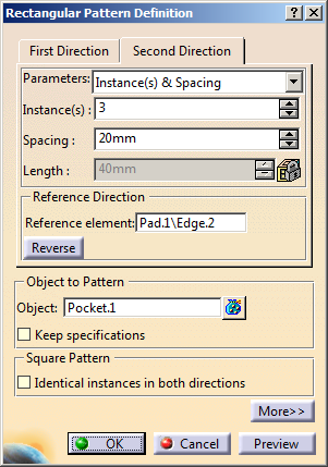
Now, click the Second Direction tab to define other parameters.
Note that defining a second direction is not compulsory. Creating a rectangular defining only one direction is possible. -
Click the Reference element field and select the edge to the left to define the second direction.
If necessary, click Reverse to make the arrow point in the opposite direction. -
Let the Instances & Spacing option: enter 3 and 10 mm in the appropriate fields.
-
Optional: Select the Identical instances in both directions check box if you want to create a pattern with equal instance in both directions.
A preview of the pattern appears in the geometry. -
Click Preview to make sure the pattern meets your needs.
Additional pockets will be aligned along this second direction.
-
Click OK to repeat the pocket's geometry nine times.
This is the resulting pattern. RectPattern.1 feature is displayed in the specification tree.
-
Let's now edit the pattern to make it more complex: double-click the pattern to display the dialog box.
-
Click the More button to display the whole dialog box.
The options available let you position the pattern.
-
To modify the position of the pockets, enter 5 degrees as the rotation angle value.
-
Click Preview.
You can notice that all pockets have moved slightly:
-
Now, modify the location of the initial pocket. To do so, enter 2 in the Row in Direction 1 field.
The application previews how the pattern will be moved. It will be moved along the direction as indicated:
-
Finally, enter 2 in the Row in Direction 2 field.
The application previews how the pattern will be moved. It will be moved along these two directions defined in steps 17 and 18:
When the Simplified representation option is on, because the pattern's geometry representation is modified, the part mass is modified too.
This option is particularly used for patterns including a large number of instances.
-
Click OK.
The application has changed the location of all pockets. Only four of them remain on the pad.
Instances and Unequal Spacing
You can assign specific spacing values between each instance by proceeding as follows:
-
Create a new pattern for the purpose of this task: select Pocket.1 as the object to pattern, and first set the Instances & Length parameter using the length values as shown here:
-
Set the Instances & Unequal Spacing parameter for the first direction.
Spacing values are displayed between each instance. -
To edit the values between each instance, you need to edit values individually. First, select the spacing of interest if not already done.
-
Then, choose one of the methods described hereafter: For example, if you wish to change 10mm for 17mm for the selected spacing, you can:
- double-click the length value in the geometry area. This displays the Parameter Definition dialog box in which you can enter the new value.
- directly enter the new value in the Spacing field of the Rectangular Pattern Definition dialog box.
-
Repeat the operation for the other spacings.
-
Click OK when done.
Create a Staggered Pattern
Create a rectangular pattern as shown below:
Note: The reference row is marked in the red color.
-
Double-click RectPattern.x in the specification tree.
The Rectangular Pattern Definition dialog box appears. -
Click More>> for more information.
The options available let you stagger the pattern. -
Select the Staggered check box in the Staggered Pattern Definition area.
By default, the option is
selected to keep the number of instances in the reference row more than
its adjacent row.
option is
selected to keep the number of instances in the reference row more than
its adjacent row.
Note: You can click to keep
the number of instances in the reference row less than its adjacent row.
to keep
the number of instances in the reference row less than its adjacent row. -
Perform any one of the following actions to define offset spacing. In the Stagger Step box, type the value to specify the offset between the alternate rows of the pattern.
- In the Stagger Step box, type the value to
specify the offset between the alternate rows of the
pattern.

The stagger step must be less than the spacing defined for the second direction. - Select the Set half of spacing check box to set the stagger step value to half of the spacing in the second direction.

Notes: - The stagger step value is set to half of the spacing in the second direction.
- If the Set half of spacing check box is selected, the stagger step value depends on the spacing in the second direction. If the spacing in the second direction is changed, the stagger step value is updated accordingly.
- In the Stagger Step box, type the value to
specify the offset between the alternate rows of the
pattern.
-
Click OK.
The staggered pattern is created.
Removing Instances
Remember that clicking an instance once removes the instance from the specifications. Clicking once or double-clicking an instance does not lead to the same result then.
- During your design, you may need to rework instances specifically. You will then have to use the Explode contextual command to delete your pattern while keeping geometry. For more information, refer to Exploding Patterns.