4-Axis
Pocketing Operations
|
|
The information in this section helps you to create and edit 4-axis pocketing
operations in your manufacturing program.
Select 4-axis Pocketing
 then select the geometry to be machined
 . .
A number of strategy parameters
 are available for defining:
Specify the tool to be used
 ,
NC macros ,
NC macros
 ,
and feeds and speeds ,
and feeds and speeds
 as needed.
4-axis Pocketing Strategy Parameters
4-axis Pocketing Machining Parameters
|
|
|
Tool path style
Indicates the cutting mode of the operation:
- Inward helical: the tool starts from a point inside
the pocket and follows inward paths parallel to the boundary.
- Outward helical: the tool starts from a point inside
the pocket and follows outward paths parallel to the boundary.
- Back and forth: the machining direction is reversed
from one path to the next
- Part offset One-way: tool motion is always done in
the same direction following paths parallel to the
boundary.
- Part offset Zig-zag: tool motion is done alternately
in one direction then the other following paths parallel
to the boundary.
|
 |
Concentric:
Builds a safe-cutting trajectory by controlling the
engagement of the tool.
The trajectory created by the
Concentric strategy adapts itself dynamically to
ensure a safe cutting at nominal speed.
The engagement
of the tool is controlled to never exceed a maximum value,
even in corner areas.
This strategy is particularly
recommended for hard-material milling.
In this type of
material(e.g. titanium, stainless steel, ceramic, ...) the
tool needs to be protected.
Other tool path styles -based
on a constant distance between passes- are not appropriate
because the tool load increases significantly when milling
the inside of a radius.
whereas the engagement is equal to the step over when
milling in a straight line.
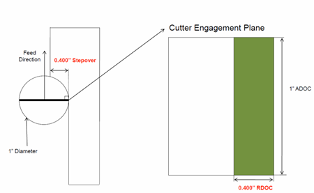
The Concentric strategy controls the tool load by
modifying the distance between passes for each motion.
As a result, the tool lifetime is increased and the
machining time is optimized. |
|
|
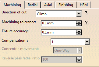
Direction of cut
Specifies how milling is to be done: Climb milling
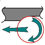 or Conventional milling
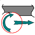
In Climb, the front of the advancing tool (in the machining
direction) cuts into the material first
In Conventional, the rear of the advancing tool (in the machining
direction) cuts into the material first.
|
|
|
Machining tolerance
Specifies the maximum allowed distance between the theoretical
and computed tool path. |
|
|
Fixture accuracy
Specifies a tolerance applied to the fixture thickness.
If the distance between the tool and fixture is less than fixture
thickness minus fixture accuracy, the position is eliminated
from the trajectory. If the distance is greater, the position
is not eliminated.
|
|
|
Limit Machining Area with Fixture
Select this check box to re-limit the area to machine
for computing tool path without jump around the check
elements. This is de-activated by default. |
|
|
Compensation
Specifies the tool corrector identifier to be used in the
operation. The corrector type (P1, P2, P3, for example),
corrector identifier, and corrector number are defined on the
tool. When the NC data source is generated, the corrector number
can be generated using specific parameters.
Movement
- When Movement is set to One-Way, the tool path
uses the selected cutting direction.
- When Movement is set to Zig-Zag, the tool
path is optimized using both cutting directions (Climb
and Conventional).
The selected cutting mode is the
main direction. Modifying it could change the trajectory.
Reverse pass (radial %)
Lets your define the reverse radial engagement when milling
in the reverse direction, that is in the direction that is
not selected as the Direction of cut.
The
value is a percentage of the main radial engagement.
A
value equal to 100% keeps the same engagement for the main
and the reverse direction. |
4-axis Pocketing Radial Stepover Parameters
Radial mode
Specifies
how the distance between two consecutive paths is to be computed:
- Maximum distance between paths
|
Distance between paths
Defines the maximum distance between two consecutive tool
paths in a radial strategy. |
Percentage of tool diameter
Defines the maximum distance between two consecutive tool
paths in a radial strategy as a percentage of the nominal tool
diameter. Depending on the selected Radial mode this value is
used as
either Tool diameter ratio
or Stepover ratio
 . .
|
|
Overhang
Allows
a shift in the tool position with respect to the soft boundary
of the machining domain.
|
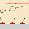
Contouring pass
For 4-axis pocketing using a Back and Forth or
Concentric tool path style, allows a final
machining pass around the exterior of the trajectory for
removing scallops. |
Contouring pass ratio
For 4-axis pocketing using a Back and Forth
or Concentric tool path style,
adjusts the position of the final contouring
pass for removing scallops. This is done by entering a percentage
of the tool diameter (0 to 50). |
4-axis Pocketing Axial Stepover Parameters
Axial strategy mode
Specifies how the distance between two consecutive levels
is to be computed:
- Number of levels without top.
|
Maximum depth of cut
Defines the maximum depth of cut in an axial strategy.
|
Number of levels
Defines the number of levels to be machined in an axial
strategy. |
Breakthrough
Specifies
the distance in the tool axis direction that the tool must go
completely through the part. Breakthrough is applied on the
bottom element, which must be specified as soft.
|
4-axis Pocketing Finishing Parameters
4-axis Pocketing High Speed Milling (HSM) Parameters
4-axis Pocketing Geometry
A 4-axis Pocketing operation can be created for machining:
- Closed pockets: the tool machines the area delimited by hard boundaries
- Open pockets: the tool machines the area that has a least one soft boundary.
You can specify the following Geometry:
- Pocket Bottom (cylindrical or conical surface) with possible
Offset on
Bottom. Bottom may be Hard or Soft.
- Pocket Boundary (edges or sketch) with possible:
- Offset on Hard Boundary
- Offset on Soft Boundary
- Offset on Contour. If you specify an Offset on Contour, it
is added to any defined Offset on Hard Boundary and Offset on Hard Boundary.
- Pocket Top (cylindrical or conical surface) with possible Offset on Top.
- Fixture or check elements with possible Offset on Check.
Note: Start points are computed automatically and are located
inside the pocket boundary. However, for open pockets, you can specify that the Start point
is to be located inside or outside the pocket. If outside the pocket, you must specify a clearance with respect to the pocket boundary.
Specifying the Pocket Boundary
The pocket boundary must be closed. It can be specified in several ways:
- If the Contour Detection contextual command is set, select the
pocket bottom. The boundary of the selected face will be proposed as pocket
boundary.
- Select the By Boundary of Faces contextual
command. In this case the
Face Selection toolbar appears to help you specify the pocket boundary.
4-axis Pocketing Tools
Recommended tools for 4-axis pocketing are End Mills, Face Mills, Conical
Mills and T-Slotters.
4-axis Pocketing Feeds and Speeds
In the Feeds and Speeds tab page, you can specify feedrates for approach,
retract, machining and finishing as well as a machining spindle speed.
Feedrates and spindle speed can be defined in linear or angular units.
A Spindle output check box is available for managing output of the SPINDL
instruction in the generated NC data file. If the check box is selected,
the instruction is generated. Otherwise, it is not generated.
Feeds and speeds of the operation can be updated automatically according
to tooling data and the Rough or Finish quality of the
operation. This is described in
Update of Feeds and Speeds on Machining Operation.
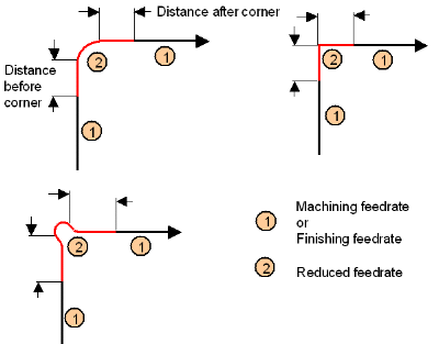
Feedrate Reduction in Corners
You can reduce feedrates in corners encountered along the tool path depending
on values given in the Feeds and Speeds tab page:
reduction rate,
maximum
radius, minimum angle, and distances before and after the corner.
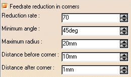
Feed reduction is applied to corners along the tool path whose radius is
less than the Maximum radius value and whose arc angle is greater than the Minimum
angle value.
For Pocketing, feedrate reduction applies to machining and finishing passes:
- for all corners in Back and forth, and Concentric mode
- for inside corners in Inward and Outward Helical modes, in offset on
Part One-Way and Zigzag, in Inward and Outward Spiral Morphing.
Feedrate reduction does not apply for macros or default linking and return
motions.
Corners can be angled or rounded, and may include extra segments for HSM
operations.
Slowdown Rate
You can use
Slowdown rate in the Feeds and Speeds tab page to reduce the current feedrate
by a given percentage.
The reduction is applied to the first channel cut and to the transitions
between passes.
Combining Slowdown Rate and Feedrate Reduction in Corners
If a corner is included in a Slowdown path, the general rule is that the
lowest percentage value is taken into account.
For example, if the Slowdown rate is set to 70 % and Feedrate reduction rate
in corners is set to 50%, the feedrate sequence is:
100%, 70% (entry in slowdown), 50% (entry in corner), 70% (end of corner, still
in slowdown), 100% (end of slowdown).
If Feedrate reduction rate in corners is then set to 75%, the feedrate sequence
is:
100%, 70% (entry in slowdown), 70% (entry in corner: 75% ignored), 70%
(end of corner, still in slowdown), 100% (end of slowdown).
4-axis Pocketing NC Macros
You can define transition paths in your machining operations by means of
NC Macros. These transition paths are useful for providing approach, retract
and linking motion in the tool path.
An Approach macro is used to approach the operation start point.
A particular case of Ramping Approach macro for pocketing is described in
Ramping Approach
macro.
A Retract macro is used to retract from the operation end point.
A Linking macro may be used, for example:
- to link two non consecutive paths
- to access finish and spring passes.
A Return on Same Level macro is used in a multi-path operation to link two
consecutive paths in a given level.
A Return between Levels macro is used in a multi-level machining operation
to go to the next level.
A Return to Finish Pass macro is used in a machining operation to go to the
finish pass.
A Clearance macro can be used in a machining operation to avoid a fixture,
for example.
Note: When a collision is detected between the tool and the part or a check
element, a clearance macro is applied automatically. If applying a clearance
macro would also result in a collision, then a linking macro is applied. In
this case, the top plane defined in the operation is used in the linking macro.
When you select Collision checking on the Geometry tab
page, the following dialog box appears.
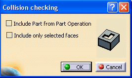
When the Include Part from Part
Operation check box
is selected, the part is retrieved from the Part Operation if part is not
defined at the Machining Operation level and used in collision check for
approach/retract macro.
By default, the check box is not selected.
When the Include only selected faces check box is selected,
faces are selected in the authoring window for collision checking. Face selection is activated only on selection of this check box, and the
selected faces are considered for collision checking with the macro.
The Include Part from Part
Operation and Include
only selected faces
options are mutually exclusive.
By default, the check box is not selected.