-
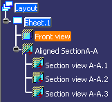
Click the front view.
-
Select Edit > Properties.
The Properties dialog box appears, displaying the following tabs: View, Visualization and Graphic.
-
Click the Graphic tab.
-
Change the required view properties and then click OK to validate.
More About the View Properties Dialog Box
This dialog box displays the following tabs:
 View
Tab
View
Tab
- Name / ID / Suffix: Enter/modify the name of the view (or
2D component reference when pertinent), an ID or/and a suffix.
You can also create a formula for the view name. For more information, refer to the Knowledge Advisor User's Guide. -
Orientation and Scale
- Angle: Define the angle between the view and the sheet.
- Scale: Define the scale of the view.
= displays the decimal value with respect to the scale. This field is read-only.
View scale should not be given as a ratio of decimal values. The required scale should be converted and given in whole numbers.
For example : 1.5:1 is not valid, instead give the scale as 3:2 or just 1.5. - Ratio: Define the display size of annotations and symbols. Both the numerator and the divisor can be modified.
-
Attributes
- Display View Frame: Show/hide the view frame.
- Lock View: Lock the view so that it cannot be modified.
Visualization
Tab
-
Hide in 3D: Select this check box if you do not want any element on the view (geometry, annotations, and so on) to be visible in the view's 3D background and in a 3D workbench (such as Part Design).
In this case, sheet elements will not be visible in Show or No Show space.The hidden element is displayed in the specification tree with a mask on the icon.
-
The mask on the icon is not applied to the children nodes, which keep their own status, with the exception of aligned/offset section cuts/views and their associated views (in this case, the mask on the icon is simultaneously applied to all the children nodes).
-
-
Background
-
Display Mode: Specify how the view's 2D and 3D backgrounds should be handled:

Standard: Shows both the 2D and 3D backgrounds.

Invisible: Hides both the 2D background (the 3D representation of 2D elements which do not belong to the current view, but to other views) and the 3D background (the representation of all 3D elements, including edges, faces and 3D wireframe).

Unpickable: Prevents selecting all elements in both the 2D and 3D backgrounds, even though you can see them. You can just handle 2D elements which belong to the current view.

Low-intensified: Dims all elements in both the 2D and 3D backgrounds.

Unpickable low-intensified: Dims all elements in both the 2D and 3D backgrounds. Additionally, although you can see these elements, you cannot select them. You can just handle 2D elements in the current view.
Refer to Managing the Layout View Background for more information.
-
-
Filter
-
Name: Select an existing filter to apply to the view. Refer to Creating View Filters for more information.
-
-
3D Grid
- Display: Select this check box to display the
3D grid in the work area. If this check box is cleared, the classic grid view is visualized.
The list next to the Display check box displays the Work On Supports (WOS).- The list displays only the name of WOS 2D which are parallel to the view plane.
- If you select multiple parallel views at the same time, the WOS 2D parallel to them are displayed.
- The list directly shows the WOS 3D.
- If you select multiple views associated to different WOS 2D which are part of a single WOS 3D, then that WOS 3D is directly selected.
- If you apply a WOS 3D to multiple views, the selected views are associated with the first compatible WOS 2D of the selected WOS 3D.
- Labels: Select the required check boxes from the following to position the labels of the grid: Top, Bottom, Left, or Right.
- Font: Select the font of the labels of the grid.
- Size: Select the font size of the labels of the grid.
- Reference: Select a reference to position the 3D grid labels accordingly.
- Grid Overrun: Select the overrun of the grid. This decides the distance at which the grid will be placed from the 2D bounding box of the view.
- Automatic Grid Size:
Select this check box to automatically select the grid size
according to the size of the view. If this check box is
cleared, the grid size is modified as follows:
- For an infinite work on support: Based on the size of the 3D background or the size of the view content.
- For a finite work on support: Based on the size of the work on support.
- Display: Select this check box to display the
3D grid in the work area. If this check box is cleared, the classic grid view is visualized.
-
Clipping
- Activate clipping frame: Check this box to clip the 3D
background of the view using a frame.
Refer to Using the Clipping Frame for more information. - Activate back-clipping plane: Check this box to clip the
3D background of the view using a back-clipping plane.
Refer to Using the Back-Clipping Plane for more information.
- Activate clipping frame: Check this box to clip the 3D
background of the view using a frame.
Graphic
Tab
- Global Properties:
- Shown: This property is not available in 2D Layout for 3D Design.
- Pickable: Select this box if you want the view to always be selectable.
- Layers: This property is not available in 2D Layout for 3D Design.
- Rendering Style: This property is not available in 2D Layout for 3D Design.
- LowInt: Select this box to apply the low-intensity color to the selected view.
Refer to Displaying and Editing Graphic Properties in the Infrastructure User's Guide for more information about these properties.
![]()