This task shows you how to create an auxiliary, offset or aligned
multi-plane section view in one go, using a profile made of multiple
segments. You can also modify them.
A multi-plane section view contains multiple sub-views, one for each
plane in the section.
This task shows you how to
-
From the Layout toolbar click View From Profile
 .
.

This command is unavailable if the active view is the main view or the background view of the current sheet.
A Tools Palette is displayed. -
In the Tools Palette, select from the following:
-
Auxiliary View: Creates a single plane auxiliary
view. For more information, see
Auxiliary View.
-
 Section View: Creates a section view.
 -
 Section Cut: Creates a section cut.
 -
 Offset: Creates offset profile for
section view or cut.
Offset: Creates offset profile for
section view or cut. -
 Aligned: Creates aligned profile for
section view or cut.
Aligned: Creates aligned profile for
section view or cut. -
 Sketch:
To create a 2D profile. This is the default
selection.
Sketch:
To create a 2D profile. This is the default
selection. -
 Selection:
To select an already existing 2D profile.
Selection:
To select an already existing 2D profile.
When Auxiliary View is selected, the Offset and Aligned commands are not available. -
-
To create a 2D profile on the fly.
- Select Sketch
.
- Select the required kind of view or cut.
- Draw the 2D profile to create the selected view.
- Double click to end the profile creation.
- An aligned section view or cut must contain at least one segment in the profile while an offset section view or cut must contain odd number of segments (minimum one).
- If your profile consists of a single segment, the multi-plane section view or section cut becomes mono-plane in nature. For more information, see Mono-Plane Section View.
- The view containing the multi-segment profile must be the current view.
- Make sure you select the first-created segment in the profile. If you do not, then only the selected segment is taken into account (and not the whole profile), and an auxiliary view is created.
- While creating profiles, you can directly select a circular geometry to detect specific constraints. For more information, see Profiles Through Circular Geometry.
- The SmartPick assistant is available for profile
creation. With this you can detect possible constraints in 2D or
3D geometries defined in the reference view or the
background. The detected constraints are not retained after the
profile creation.
Press Shift key to disable the detection of constraints. Press Ctrl key to keep the detected constraints. - The view created by sketching the profile is associative to the profile, by default.
- Select Sketch
- To select an already
existing 2D profile.
- Click Selection
.
- Select the required kind of view or cut.
- Select the required kind of profile.
- Select a 2D profile in the active view.
- You can also select the profile in active view without selecting the required kind of view or cut. The profile type is computed based on the number of segments and their alignment.
- The view created by selecting the already
existing 2D profile is not associative to the
profile.
- Click Selection
-
Click on the sheet at the location where you want the section view to be positioned.
- You can position the view independently anywhere in the sheet.
- Positioning the view defines the section view direction, in
accordance with the projection method.
The projection method (First angle standard or Third angle standard) is defined by the sheet style, as specified in the standard used by the layout. For more information, refer to Sheet Styles in the Administration Tasks chapter. You can change the projection method by editing the layout sheet properties (using Edit > Properties). - Section/auxiliary views are always created using the scale of the current view.
- If you change the sheet scale (defined in the sheet properties), the scale of all existing views (defined in the view properties) is multiplied by that of the sheet (for example, if existing views already have a scale of 1/10, and if you change the sheet scale to 1/10, then existing views will now have a scale of 1/100).

Note: Notice how the view is previewed in the part window. You need to zoom out, as the view box defined in the ISO_3D standard used by the current layout has sides of 1000mm. For more information on the standards, see Administration Tasks.
The section view is created, with its plane perpendicular to the active view. Also, the section view node is added to the specification tree.
The section view so formed is associative to the profile, by default. You can isolate the view later.
The multi-plane section view is created and is represented in the specification tree along with its sub-views as child nodes. The corresponding callout is automatically created in the current view identical to the profile. The sub-views share the same origin in the layout sheet, and their local axes (H and V) overlap. If you selected Section View, the result is as shown below:
Create a Profile View |
|
-
Double-click the callout in the profile view.
-
In the Tools Palette, click one of the following:
Options Description  Replace Profile
Lets you replace the profile.  Reverse View Direction
Reverses the direction.  Manipulation in one direction according to the callout
Modifies the callout extremities only along the callout direction.  Manipulation in two directions according to the callout
Modifies the callout extremities and offsets the callout in both the directions. By default, this option is selected. In case of perpendicular callouts, only Manipulation in one direction according to the callout
is available. -
Click Replace Profile
.Tip: You can also access this command from the contextual menu of the view. Right-click the node of the view, Section view X-X in the specification tree to access the contextual menu. Then select Section view X-X object > Replace Profile. This is also available for auxiliary views. -
Redraw the profile.
The profile is replaced and the view is modified interactively.Note: You can replace a profile by a similar kind only. For example: an offset profile can be replace only by another offset profile. -
Click Reverse View Direction
to reverse the direction of the callout.
Tip: You can also access this command from the contextual menu of the view. Right-click the node of the view, Section view X-X in the specification tree to access the contextual menu. Then select Section view X-X object > Reverse View Direction. This is also available for auxiliary views. -
Click
Manipulation in one direction according to the callout
or Manipulation in two
directions according to the callout
.
Manipulation in one direction according to the callout Manipulation in two directions according to the callout 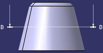
White handles appear.
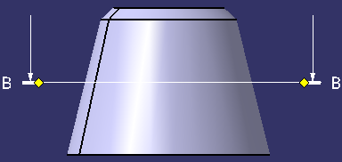
Yellow handles appear.
Press the Ctrl key to move the second callout extremity simultaneously. In this case, the second callout extremity moves in the opposite direction.
- You can move the extremities only along the callout's support. However, you cannot modify the callout's support itself, as it's just a representation of a view's specifications.
- You cannot move a callout extremity beyond the other extremity. In this case, the other extremity also moves (both the extremities are coincident).
- Right-click the node of the view, Section view X-X or Auxiliary View X in the tree to access the contextual menu.
- Select the Change View Support option to change the view support of the profile view. For more More about Change View Support Box.
Modify a Profile View |
|
![]()