|
This topic provides more information on profile views in terms of the
2D profile, multi-plane section views, mono-plane section views, and
auxiliary views. The
following topics are discussed:
|
|
What Are Offset or Aligned Multi-Plane Section Views?
|
 |
This sub-topic explains what offset or aligned multi-plane section views
are.
A multi-plane section view is a section view that has multiple planes.
It can be either:
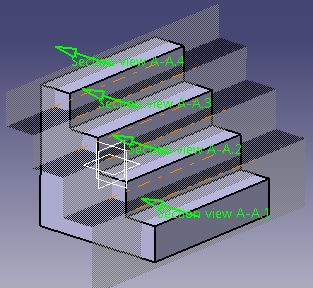
- An offset section view (with multiple planes parallel to each
other).
- An aligned section view (with multiple planes that are secant by
pair).
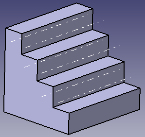
In both examples shown above, the section view profile contains three
segments. The red point is the origin of the first view, the blue point
the origin of the second view and the green point the origin of the
third view. These three points will be projected at the same position in
the multi-plane section view, and this position will be the origin of
the sub-views.
These sub-views contain the actual geometry and annotations created
in the multi-plane section view (you cannot create geometry or
annotations outside a sub-view). |
|
Display of Sub-Views in the Specification Tree
|
|
By default, the sub-views are not displayed in the
specification tree. The sub-views of sections created before V5-6R2017
(R27) release are displayed in the specification tree.
To display them, right-click a section view in the specification tree
and select Properties. In the Properties dialog
box, switch to Visualization tab and select Display
sub-views in specification tree.
You can also select Tools > Options > Mechanical > 2D Layout for 3D
Design > View Creation tab > Multi-planes Section View > Display
sub-views in specification tree.
 |
Tips: |
| |
Right-click the section view and select Sub-views > Sub-view.x
to perform the following operations:
- Access the sub-view properties
- Activate the sub-views (Not available for sub-views of
monoplane section)
- Edit or change the view filters
- Display and resize boundaries
- Display view plane in 3D
- Display View Plane/Profile in 3D
- Restore show state
|
|
| |
For a monoplane section view, right-click the view and select
the subview to access the related properties. |
|
|
Hide or Show Section View and its Sub-Views
|
|
- If a section view is in Show mode, the visibility
of the sub-views depends on their individual Hide/Show
status.
- If a section view is in Hide mode, the sub-views are
hidden irrespective of their individual Hide/Show status.
|
|
Sub-View Boundaries
|
|
This sub-topic makes miscellaneous remarks about multi-plane section
views:
General Remarks about Sub-View Boundaries
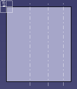
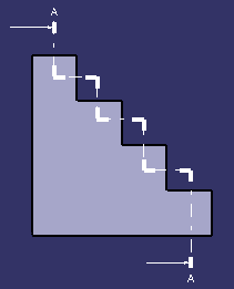
Each sub-view has two boundaries corresponding to
the segment end points of the clipping profile.
Take the following section, for example.
The resulting boundaries are the following:
Display of Sub-View Boundaries
By default, when the multi-plane view is created,
the first boundary of the first sub-view and the last boundary of
the last sub-view are hidden.
You can change this default behavior. From Tools > Options >
Mechanical > 2D Layout for 3D Design > View Creation tab >
Multi-planes Section View area, select Display all
boundaries but extreme ones.
You can show or hide all the boundaries in a multi-plane section
view, by right-clicking the view and selecting Section View
object > Display Boundaries or Section View object > Mask
Boundaries from the contextual menu.
You can also show or hide boundaries on a given
sub-view, or on a selection of sub-views, by right-clicking the
required sub-views and selecting View object > Display First
Boundaries or View object > Mask Second Boundaries.
Note: The Hide/Show command has no
effect on boundaries
Resize of Boundary Segments
You can shorten or extend the length of a boundary
segment. To do so, select the boundary segment. Two manipulators are
displayed at each end. Drag them to resize the boundary segments as
wanted.
You can resize several boundary segments at once by
multi-selecting them. In this case, pressing the Ctrl key
while manipulating resizes all the boundaries to the same length.
You can also bring back the resized boundary length
to the original default length, by right-clicking the view and
selecting Section View object > Resize Boundaries On View
Background. |
|
| |
3D Visualization
|
|
This sub-topic explains how the section view/cut and its sub-views can
be displayed in 3D.
Display View in 3D
You can view the sub-views in 3D according to the 2DL section
view.
Right-click the view and select 3D Visualization > Display View
in 3D.
|
Display View Plane/Profile in 3D
You can now view all the sub-view planes in 3D according to
the profile of 2DL section view.
Right-click the view and select 3D Visualization > Display
View Plane/Profile in 3D.
|
|
|
Multi-Plane Section View and Sub-View Properties
|
|
This sub-topic deals with the properties of multi-plane section views
and sub-views.
You can edit the properties of a multi-plane section view or
sub-view by right-clicking it and selecting Properties. Only
specific properties are detailed below.
The following are discussed:
Multi-Plane Section View Properties
In the Properties dialog box for
multi-plane section views, the View tab and the
Visualization tab offer options that are specific to
multi-plane section views. For options that are not specific to
multi-plane section views, refer to
Editing View Properties.
View tab
- Name: Specify the
name of 2DL multi-plane section
view.
- Angle: Define the
angle from the sheet horizontal
axis for all the sub-views of
the 2DL multi-plane section
view.
- Scale: Set the
scale of all the sub-views of
the 2DL multi-plane section
view.
- Display View Frame:
Show/hide the sub-view
frame.
- Lock View:
Lock the sub-view so that
it cannot be modified.
|
 |
You cannot edit the position, scale and rotation of
sub-views. They are modified by editing the multi-plane
view properties. |
Visualization tab
- Display all boundaries:
Select this option to display
all the boundaries in the
sub-views.
- Color: Choose the
color of the boundaries. By
default, it is white.
- Line type: Choose
the line type of the boundaries.
By default, it is 4.
- Thickness: Choose
the thickness of the boundaries.
By default, it is 1.
|
Multi-Plane Section Sub-View Properties
In the Properties dialog box for
multi-plane section views, the Visualization tab
offers options that are specific to multi-plane section
sub-views. Other tabs offer no specific options and are detailed
in Editing View Properties.
- Filter: Select
the name of the filter applied
to the sub-view.
Note: Only display filters can
be applied to sub-views.
- Boundaries:
Select the boundaries to be
displayed in the sub-view.
|
|
|
|
Miscellaneous Remarks About Section Views
|
|
This sub-topic makes miscellaneous remarks about multi-plane section
views.
|
| |
Modifiable Mono-Plane Section View
This sub-topic makes remarks about mono-plane section view.
- If the section view profile consists of a single
segment, the section view is a mono-plane section view.
- The profile view is associated to the 2D profile. This
is a default behavior. So when you modify the sketch of the
section view, the view is modified accordingly.
- You can:
- Associate the profile view to the view
- Isolate the profile view from its reference
view
- Change the profile view support
|
- If the reference view is deleted, a warning message
appears prompting that the associativity will be broken.
- When a modifiable mono-plane section view is created, a
sub view with a clipped background is created.
- You can access the back clipping plane, 2D visualization
mode, and the clipping frame from the the modifiable section
view (and not the sub-view). To access them, open the
contextual menu of the section view from the node in the
specification tree.
- In the specification tree, the symbol of a mono-plane
section is masked with the following to denote special
cases:
- A red profile across the icon: if the view
is created from a 2D profile
- A lightning bolt: if the view is isolated
from the plane or the 2D profile
|
|
|
| |
Modifiable Auxiliary View
This sub-topic makes remarks about modifiable auxiliary view.
- It is a view component whose 3D plane is decided by
a single segment profile.
- The profile view is associated to the 2D profile.
This is a default behavior. So when you modify the
sketch of the section view, the view is modified
accordingly.
- You can:
- Associate the profile view to the view
- Isolate the profile view from its reference
view
- Change the profile view support
|
- You can access the back clipping plane, 2D
visualization mode, and the clipping frame from the the
modifiable section view (and not the sub-view).
- If the reference view is deleted, a warning message
appears prompting that the associativity will be broken.
- In the specification tree, the symbol of an
auxiliary view is masked with the following to denote
special cases:
- A red profile across the icon: if the
view is created from a 2D profile
- A lightning bolt: if the view is
isolated from the plane or the 2D profile
- No masking: if the view is created from
a reference plane and is associative to it
|
- You can invert the view direction.
|
|
| |
Profiles Through Circular Geometry
This sub-topic makes remarks about profiles which pass through
the circular geometry. According to the type of profile to be
created, the detected constraints are different.
- For an offset section view or cut
- When the circle is selected before
selecting the start point: A line passing
through the center of the circle appears.
You can click along this line to select the
start and the end point of the segment of
the profile
- When two circles are selected
consecutively before
selecting the start point: A line passing
through the centers of both the circles
appears. You can click along this line to
select the start and the end point of the
segment of the profile.
- When a circle is selected after
selecting the start point: A line passing
through the center of the circle and this
point appears. You can click along this line
to select end point of the segment of the
profile.
- When two circles are selected
consecutively after
selecting the start point: The first and the
middle segment are automatically created.
You can select the end point to complete the
section view or cut.
- When at least two points of the profile
are already selected and then a circle is
selected consecutively: The first and the middle segment
are automatically created. The third segment
is partially created as a line passing
through the center of the circle appears.
You can select the end point to complete the
profile
 . .
|
- For an aligned section view or cut
- When the circle is selected before
selecting the start point: A line passing
through the center of the circle appears.
You can click along this line to select the
start point. The second point is
automatically on the center of the circle.
You can then select the third point, as
required.
- When two circles are selected
consecutively before
selecting the start point: A line passing
through the centers of both the circles
appears. You can click along this line to
select the start point. The second point is
automatically on the center of the second
circle.
- When a circle is selected after
selecting the start point: The second point
is automatically on the center of the
circle.
|
|
|
| |
About Modifying a Profile View
When working with translation of the profile:
- White square manipulators appear at the end of the segments.
- You can only move the extremities along the support. You
cannot change the support itself.
- You can press the Ctrl
key to move both the extremities together by the same distance.
That is, if you move one extremity keeping the
Ctrl key pressed, the other
extremity moves in the opposite direction
|
When working with manipulation in two directions according to the
callout, yellow diamond manipulators
appear at the end of the segments.
When working with manipulation in one direction or two directions
according to the callout:
- When you hover the pointer on a segment the pointer
shows the rough direction of allowed movement or if there is
no movement possible.
- You can press the Shift
key to snap the position of extremities or folding lines on
the grid.
|
|
|
") |