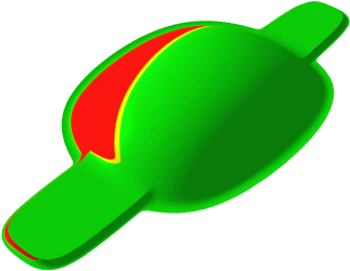
The split analysis separates the splitable part of a surface from its non-splitable part to identify the transition areas. The drawing vector determining the split direction, and the split angle can be defined by using the Light Source Manipulator.
- Green: Splitable area
- Yellow: Transition (grey wash) area
- Red: Non-splitable area
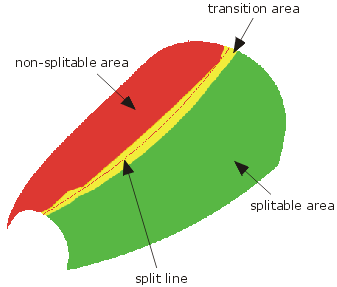
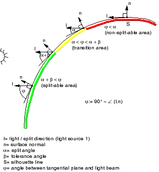
Computation of splitable and non-splitable areas
Important: Before carrying out the split analysis, all the surface normals have to be adjusted to
the 'exterior'.
|
-
Click the Split Analysis icon
 .
.The 'Split Analysis' dialog box is displayed.
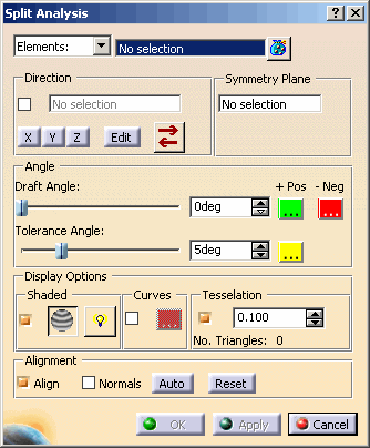
- Selection Type:
- Elements: With this option, the selection field for individual element selection is displayed.

The analysis is applied to the selected elements. - Display List: With this option, a combo box containing all defined Display Lists
is displayed instead of the selection field.

When selecting a display list, all stored elements in this set will be used as input for the analysis.
If the selected display list is modified, the analysis will automatically be updated.
- Elements: With this option, the selection field for individual element selection is displayed.
- Direction: see Defining a direction
- Symmetry plane: For the selected geometry can be selected a symmetry plane at which the geometry is mirrored.
- Angle
- Draft Angle: Setting of the Draft angle regarding the light source (0° to 90°).
 +Pos and
 -Neg: Definition of the colors for the graphical
display of surfaces which are deemed to be positive (larger than the specified Draft angle) or negative (lower than
the specified Draft angle).
- Tol. Angle: Setting of the grey wash (transition) area (0° to 10.0°).
 : Definition of the color for the grey wash area.
Analysis result with Split Angle = 0° Analysis result with Split Angle = 7° 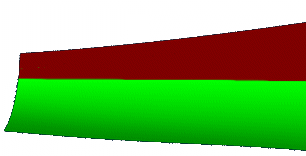
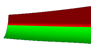
- Draft Angle: Setting of the Draft angle regarding the light source (0° to 90°).
- Display Options: Display of the split analysis. The options 'Shaded' and 'Curves' can be active simultaneously
(see figure Display of the split analysis).
- Shaded
- ON: A shaded analysis is automatically displayed to the selected elements (default).
- OFF: The shading is switched off.
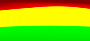
 Anti-Alias:
Smoothing the edges of the shaded split analysis lines by an anti-alias.
Analysis result WITHOUT Anti-Aliasing Analysis result WITH Anti-Aliasing 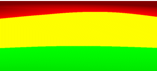
 Enable Lighting: Setting the shading
mode for the split analysis. The shading mode is saved in the feature as graphic property.
Enable Lighting: Setting the shading
mode for the split analysis. The shading mode is saved in the feature as graphic property.- OFF: The brightness values are equal for each pixel. This has the advantage that the analysis is displayed independently from the light source settings.
- ON: The analyzed surfaces are shaded using the current light source settings. Due to the different
brightness values, the display has a stereoscopic effect.
Analysis result WITHOUT Enable Lighting Analysis result WITH Enable Lighting 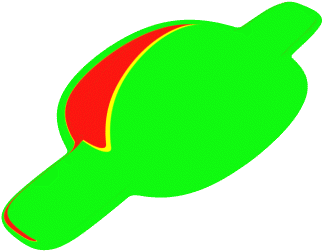
- Curves
- ON: The split line will be displayed (default). This analysis curve will be calculaed at the point where
the exact split angle occurs at the bottom end of the angle tolerance defining the grey wash area.
The quality of the result depends on the setting of the option 'Tesselation'. - OFF: The split line will not be displayed.
 : Definition of the split line color.
- ON: The split line will be displayed (default). This analysis curve will be calculaed at the point where
the exact split angle occurs at the bottom end of the angle tolerance defining the grey wash area.
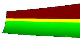
- Tesselation: Defines the accuracy for the triangle calculation to improve the quality of the shaded split
analysis.
Shaded Split Analysis with approx. 50 Triangles Shaded Split Analysis with approx. 20000 Triangles 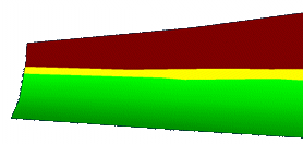
- Shaded
- Alignment
- Align: The capability to align the input element normals can be toggled.
- Normals: The display of the input elements normals can be toggled.
The normals are displayed as direction manipulators, one for each input element, defining the orientation of the element.
With an invert handle at the manipulator the orientation of a single input element can be inverted to flip the splitable and non-splitable parts of the surfaces. - Auto: Aligns automatically the normals of the input elements.
- Reset: Pushing this button will reset the orientation of input elements, i. e. restores their 'natural' orientation.

