doctype html public "-//w3c//dtd html 4.0 transitional//en"> Mapping Shapes

Mapping Shapes

This task explains how to map a set of surfaces on a reference surface to a target surface. Geometry elements relating to a reference can be adapted to a target of the same type.

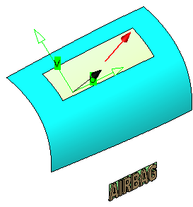
A set of surfaces is first projected onto a reference surface and then mapped onto a target.
The shape of the mapped geometry is adapted and scaled to fit the target.

Normal and UV orientation of the target are taken into account when mapping. If necessary, these parameters can be modified using the Invert shell normal and Swap UV options of the Invert command to obtain the desired result.
Open the ShapeMapping.CATPart document.
  In the example used, a logo consisting of a set of surfaces and lying on a reference surface shall be mapped to a target surface.
  1. Create a surface on the target base surface using the Geometry Extraction command.

As target is frequently used a part of a base surface. Using the Geometry Extraction command, you can extract a part from a surface with four iso-parametric curves as boundaries.
 
  1. Increase the order of the target surface to 16 x 16 using the Order command.

  2. Invert the surface normal of the target surface using the Invert (Datum) .
    command to define the correct direction for the mapping operation.

  3. Click Swap UV in the 'Invert' dialog box to invert the target surface orientation.

  4. Rename the extracted surface to 'Target'.

 
  1. Click the Shape Mapping icon .
    The 'Shape Mapping' dialog box is displayed.


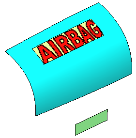
  1. Select 'Logo Surface' as Element, 'Reference Surface' as Reference, and 'Target' as Target.

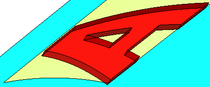
  2. Click Apply to map the logo onto the target surface.

    The result is strongly waved.


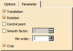
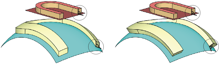
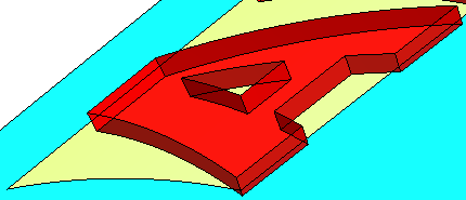
  1. Select the Translation check box on the Parameter tab and click  Apply.

    The deformation is removed.

 
  1. Select the Rotation check box on the Parameter tab and click Apply.
    The mapped logo is rotated in a way that the angle between result and target is the same as between original logo and reference.


  1. Click OK to terminate the mapping operation.

You can define the following options:
  • Element: Select the geometry elements to be mapped.
  • Reference: Select the reference surface.
  • Target: Select the target surface, onto which the elements shall be mapped.
  'Options' tab
 
  • Projection: Specifies the type of projection from the geometry elements to the reference.
    • Normal: The projection is done in the direction of the surface normal in the selected point.
    • Along a Direction: The projection is done in the direction of the vector defined in the field 'Direction'.
  Parameter tab
 
  • Translation: The distance between result and target equals the distance between input element and reference.
 
  • Rotation: The angle between result and target equals the angle between input element and reference.
 
  • Control Point: Only control points covering the reference are modified, geometry areas outside the reference remain unchanged.
  • Smooth Factor: Specifies a smooth factor for an enhanced control point distribution.
    Warning: G0 continuity between the resulting elements among each other and the target can get lost.
  • Min. Order: Specifies the minimum order of the input elements which is adopted by the result.
    The order of the input elements is increased until this value if it is below.
  • Crop: Crops underlying surfaces of mapped faces to its minimal extent.