|
Open the Order.CATPart document. |
 |
-
Click the Order icon  . .
The Order dialog box opens.
|
 |
| |
-
Select the surface Fend-15.
The Local order text boxes are active.
The global order options are not available, as only one element is selected.
-
Click the Analyze button.
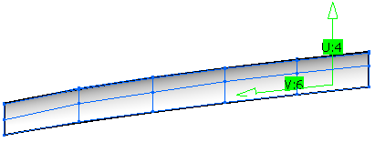
The minimum and maximum order values in U (4 for Min and Max) and V (6 for Min and Max) direction are displayed in the
Analyze Orders frame.
-
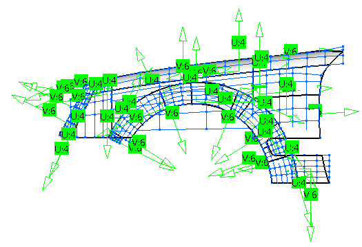
Select the Symbols check box.
The U and V order values and directions are displayed in the graphics area.
|
 |
| |
-
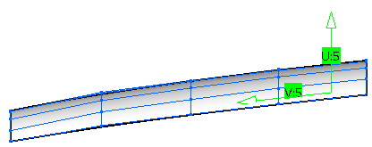
Increase the order in U direction to 5 and decrease the order in V direction to 5.
A preview of the modified order is displayed in the graphics area.
-
Click Apply to set the new order values.
|
 |
| |
-
Set all surfaces of the current geometrical set to Show mode.
-
Select all surfaces.
The Global order text boxes are active.
-
Click the Analyze button.
The minimum and maximum order values in U (4 for Min and Max) and V (6 for Min and Max) direction are displayed in the
Analyze Orders frame.
-
Select the Symbols check box.
The U and V order values and directions are displayed in the graphics area.
The surfaces have different order values.
|
 |
| |
-
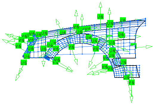
Specify a global order of 6 in U and V direction and click Apply.
The order of all selected surfaces is set to 6 in U and V direction.
|
 |
 |
You can define the following options:
- Elements: Selects elements whose order shall be changed.
Valid inputs are surfaces, faces, and curves.
- Local order: Default option for a single element. Only available if a single element is selected. If selected,
all other order options are disabled.
Modifies the U and V order values of one surface OR the U order value of one curve.
When the order of an element is reduced, the end/edge conditions should be maintained as close to the original as possible.
- Global order: Modifies globally the order of multiple surfaces OR curves to the U and V values defined in one
operation.
Only available, if multiple elements are selected and the options 'Max. Order' and 'Min. Order' are inactive.
- Min. order: Specifies globally the minimum order of multiple surfaces OR curves to the U and V values defined
in one operation.
Only the order of selected elements with a lower order than specified is increased. Elements with higher order than specified
remain unchanged.
Only available, if multiple elements are selected and 'Global Order' and 'Max. Order' are inactive.
- Max. order: Specifies globally the maximum order of multiple surfaces OR curves to the U and V values defined
in one operation.
Only the order of selected elements with a higher order than specified is decreased.
Elements with lower order than specified remain unchanged.
Only available, if multiple elements are selected and 'Global Order' and 'Min. Order' are inactive.
 Linking U and V: Links the U and V values by selecting
this button. The V box is disabled. Values can only be modified in the U box. Linking U and V: Links the U and V values by selecting
this button. The V box is disabled. Values can only be modified in the U box.- Analyze: Analyzes all selected elements and reports the minimum and maximum values for both U and V in the corresponding
boxes.
- Symbols: Displays symbols indicating the U and V order values and U and V orientation in the graphics area.
|
| |
Click 'More Info' to display deviations. |
 |
| |
- Display: Switches on and off globally the graphical display of the deviation values.
- Static, None: See Apply Modes
- Deviation - Max.: Displays the maximum deviation of all the results after the change in order has been applied.
In the graphics area are displayed the individual deviation values at any position where deviations occur.
|
|

|