|
This task explains how to invert and align the normals and directions of selected curves and surfaces.
|
 |
In the graphics area, the following vector symbols are used to display the UV and normal directions:
 |
- green: UV direction
- black: surface normal depending from the UV vectors
- red: shell normal (basis for the basic direction of the commands applied in the following on the surface)
|
| |
|
With this command, the following invert operations can be carried out:
|
 |
Invert (Feature)
|
| |
After having carried out the inversion, a Feature element 'Invert.X' is inserted in the specification tree and
the original elements are set to Hide mode.
The input geometry will not be modified.
For certain modes (Align Normals to Surface Normal, Align UV,
Align Directions), the input geometry must be topologically contiguous (see
Gap Distance). |
 |
 |
Invert (Datum)
|
| |
With this command, the inverted elements remain datum elements.
If the command is carried out on a datum element, the result will be applied directly on the input element.
The selected elements need not to be topologically contiguous, however, in case of carrying out the command with a selected
Reference, only the region containing the reference element will be considered. |
 |
|
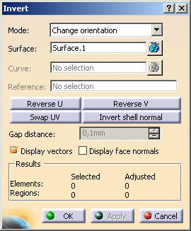
You can define the following options:: |
| |
Mode
For inverting surfaces and curves, you can select the following modes:
- Change orientation:
Changes the orientation of surfaces. In this mode, the following options are available:
- Reverse U/V: Inverts the U or V direction of all selected surface elements.
 |
Attention:
Inverting U or V direction also inverts the surface normal! |
- Swap UV: Inverts the U and V directions of all selected surface elements.
|
Attention:
Inverting UV direction will also invert the surface normal! |
- Invert shell normal: Inverts the shell normal direction of the selected surface
elements.
 |
Note: In case of constructions on top, this option is not available for subsequent edition, as updates cannot
be guaranteed to be free of errors. |
- Align normals to surface normal: Aligns all normals, i. e. shell and surface normals
of all selected surfaces lying within one topologically contiguous region (see Gap Distance) according
to the surface normal direction of the surface selected as Reference.
|
Note:
In order to be able to select a reference, it may be necessary in certain constellations to use
the selection filter 'Geometrical Element Filter' (see Selecting
Using a Filter). In some special cases, e. g. a federated join (see
Using the Federation Capability) as
input element, the selection of a reference may not be possible. |
- Align UV: Aligns U and V direction of all selected surface elements lying within one region
(see gap distance) according to the U and V direction of the surface chosen as a
Reference.
The surface normal direction remains unchanged.
- Invert direction: Inverts the direction of the selected curve elements.
|
Note: In case of constructions on top, this option is not available for subsequent edition, as updates cannot be guaranteed
to be free of errors. |
- Align directions: Aligns the direction of all selected curve elements lying within
one region (see gap distance) according to the direction of the curve chosen as a
reference.
|
| |
- Surface: Selects the surfaces to be inverted.
- Curve: Selects of the curves to be inverted.
- Reference: Only available for the options Align direction,
Align normals and Align UV.
Selects from the selected surface or curve element the reference element specifying the normal direction, UV alignment, and
curve direction.
- Gap distance: Only available for the options Align direction,
Align normals and Align UV.
If the distance between selected surfaces is larger than the specified tolerance value, they are assigned to different regions.
Curves and surfaces cannot be mixed.
To preserve all surfaces, the minimum from the specified gap tolerance and the smallest edge of the surfaces concerned is
used.
- Display vectors: Displays the normal vectors,
the U and V direction arrows on a surface, and
the direction vectors of a curve.
To distinguish the different vectors the following colors is used:
- UV directions: green
- Shell normals: yellow
- Surface normals: white
- Display face normals: This display option is enabled if the Display vectors option is selected.
The face normal is displayed for each input face. To distinguish the different normals the following colors is used:
- Shell normals: red
- Surface normals: white
- Face normals: light blue
- Results: Displays the number of selected and adjusted elements as well as the number of regions after a multi-selection.
|
|

|