You can add a leader to geometrical elements associated with the annotation or anywhere apart from geometry. After adding a leader to an annotation, you can specify breakpoints and and add extra leaders from breakpoints. You can also add 3D leaders or switch current 2D leaders to 3D to position them outside the annotation plane.
Adding Leaders and Using Breakpoints
- Improve the highlight of the related geometry, see Highlighting of the Related Geometry for 3D Annotation.
-
Right-click the annotation text and select Add Leader from the contextual menu.
-
From the Tools Palette, select the required type of the leader to be created.
- 2D: lets you create a 2D leader in the current annotation plane.
- 3D: lets you create a 3D leader with its arrow end at any selected position on the associated element with annotation. The yellow diamond at the leader end is always parallel to the screen.
- 2D/3D: lets you create a 2D leader in the current annotation plane or 3D leader with its arrow end at any selected position on the associated element with annotation.
-
To specify the arrow end of a leader, select a geometrical element as support, for example a face.

- In case of section views, you can choose the extreme point for leader at z=0 or z<0 positions.
- In case of section cuts, you can choose the section plane (z=0).
- In case of 2D leader, you can select the yellow geometrical elements (point, line, or curve) displayed to represent the intersection between the geometrical elements associated with the annotation and the annotation plane.
- In case of 3D leader, you can click anywhere in the work area.
- In case of 2D/3D leader, you can select the yellow geometrical elements (point, line, or curve) to create 2D leader or click anywhere in the work area to create a 3D leader.
- You can right-click the arrow end of the 2D leader and select Switch to 3D Leader to switch the leader from 2D to 3D. When you switch to the 3D leader, the diamond symbol at the extremity of the leader displayed parallel to screen.
- You can add 3D leaders for following
annotations:
Semantic Annotations
Non-Semantic Annotations
Text with Leader
Flag Note with Leader
Datum Feature
Datum Target
All Geometrical Tolerances
Surface Texture
Text with Leader
Flag Note with Leader
Datum Feature
Datum Target
Datum Target
Note Object Attribute
Note Object Attribute instantiation
Geometrical Tolerance
Welding Symbol
Surface Texture
Coordinate Dimensions
- You can select preferences to specify the positions of the annotation body and the arrow end of the leader . For more information, see Dimension Default Position Along Normal View.
-
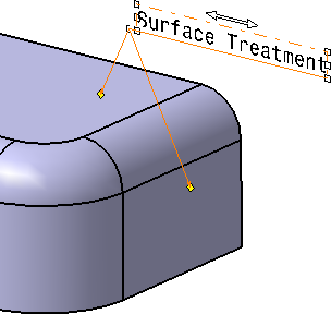
Click the face as shown to begin the leader (arrow end).
Then new leader appears. 
-
If needed, position the leader at the desired location by dragging it.
-
Right-click the end point of the arrow end and select Extremity Link > Perpendicular to add the perpendicular extremity.
The leader, for which extremity is added, moves based on the movement of annotation in order to keep the specified extremity.
Before Adding Extremity Link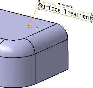
After Adding Extremity Link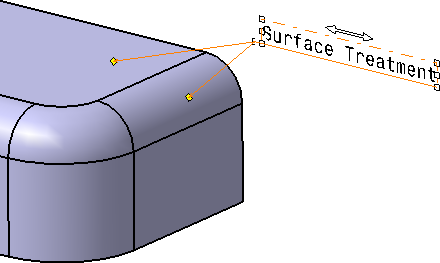
After Moving the Annotation Behavior of Arrow with Extremity Link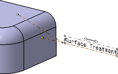
After Moving the Annotation Behavior of Arrow with Extremity Link -
Right-click the end point of the arrow and select Extremity Link > Remove to remove the extremity added.
When you remove the extremity, you can place the end point of the leader anywhere in the work area. -
To add an extremity link again, right-click the end point of the arrow, select Add Extremity Link, and then any reference element associated with the annotation.
You cannot add an extremity link for any annotation not associated with any geometrical element. -
To add a breakpoint, right-click the manipulator at the extremity of the arrow end and select Add a Breakpoint.

The breakpoint appears as yellow diamond. You can select it and drag the leader. 
-
To add a leader from the breakpoint, right-click the breakpoint and select Add an Extremity and select any geometrical element associated the annotation to add the extremity.
This command is only available for text and flag note annotations.
-
Right-click the end point of the newly added leader and select Extremity Link > Perpendicular to add the perpendicular extremity.
- For an annotation on which a leader is added from a breakpoint, you can add an extremity link to any geometrical element associated with that annotation.
- If the leader extremity is perpendicular to a reference, an orientation link is created between the leader and the reference.
-
Right-click the end point of the arrow and select Extremity Link > Remove to remove the extremity added.
When you remove the extremity, you can place the end point of the leader anywhere in the work area. -
Click the face as shown to begin the leader (arrow end).
The leader appears. 
-
To add an extremity link again, right-click the end point of the arrow, select Add Extremity Link, and then any reference element associated with the annotation.
- When you add an extremity link, the extremity points cannot be moved but when you move the annotations, leaders are adjusted accordingly.
- When the breakpoint is added, according to the position of the breakpoint, the leader extremity is adjusted.
sas
Moving and Positioning Leader Breakpoints
|
|
You can also activate or deactivate the Snap on Privileged Direction option from the 3D Grid toolbar. See Using a 3D Grid. |
Open the document that contains a text with leader and a balloon. Add a breakpoint to both annotations, as explained in the previous section.
-
Move the text leader breakpoint with the mouse. You can position the leader breakpoint anywhere, and snapping is not used.
-
Now, press the Shift key while moving the leader breakpoint with the mouse. The leader is snapped, and is positioned vertically or horizontally, or perpendicular to the element to which it is attached.
-
Release the Shift key and the mouse when you are satisfied with the position of the leader.
-
Move the balloon leader breakpoint with the mouse. You can position the leader breakpoint anywhere, and snapping is not used.
-
Now, press the Shift key while moving the leader breakpoint with the mouse. The leader is snapped, and is positioned vertically or horizontally, which happens to be the same orientation as the element to which the leader is attached.
-
Release the Shift key and the mouse when you are satisfied with the position of the leader.
Both leaders are now positioned properly.
- You can undo or redo the operations performed on an annotation. Each time
you manipulate an annotation, an undo step is created in the Undo with history
 panel.
 - An undo step is not created for the Free Rotation
 operation performed on an annotation.
 - When manipulating the extremity leader, if the leader has a positional link on a reference, only the snap on perpendicular to the reference and reference tangent directions are available. When there is no reference selection, snap on horizontal and vertical directions is available.