 |
| This page deals with the options concerning:
|
View/Annotation Plane Associativity
|
 |
| Defines the View/Annotation Plane associativity options: |
Create views associative to geometry
|
| Creates views associative to the geometry, so that views
and their annotations are automatically updated when the geometry is
modified. |
 By default, this option is selected.
 |
 |
|
|
 |
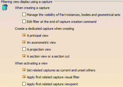
When creating a capture:
Defines behaviors during capture creation:Manage the visibility of Part
instances, bodies and geometrical sets
|
Defines whether the visibility status of 3D part instances
in products, bodies and geometrical sets in 3D part is managed by captures.
 |
The same option is available in the Capture Attributes
tab of the capture properties. |
 By default, this option is not selected.
 |
Edit filter at the end of capture creation command
|
| Edit the capture filter by opening the Filter workshop once the capture created. |
 By default, this option is not selected.
 |
Create a dedicated capture when creating:
|
A principal view
|
| Creates an associated capture when creating a principal
view. |
 By default, this option is selected.
 |
An axonometric view
|
| Creates an associated capture when creating an axonometric
view. |
 By default, this option is selected.
 |
A projection view
|
| Creates an associated capture when creating a projection
view. |
 By default, this option is not selected.
 |
A section view or Section Cut view
|
| Creates an associated capture when creating a section view
or section cut view. |
 By default, this option is selected.
 |
When activating a view
|
Set related capture as current and unset others
|
| Sets as current the capture associated with an
activated view and, at the same time unsets other captures. |
 By default, this option is selected.
 |
Apply first related capture visual filter
|
| Applies to the view its first related capture filter. |
 By default, this option is selected.
 |
Apply first related capture view point
|
| Applies to the view its first related capture viewpoint. |
 By default, this option is not selected.
 |
 |
|
|
 |
When selecting a reference element:
|
Change primary view plane
|
|
Allows you to change the principal view plane element during the view
creation. |
 By default, this option is selected.
 |
Resize view box according to 3D model
|
Resizes the view box once you have selected an element.
|
 By default, this option is selected.
 |
 |
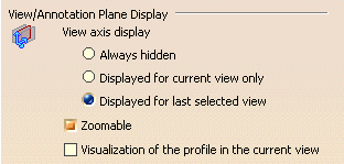
View/Annotation Plane Display
|
 |
| Defines the View/Annotation Plane display options: |
Always hidden
|
| Defines the annotation plane axis system to be
hidden for all the views. |
 By default, this option is not selected.
 |
Displayed for current view only
|
| Defines the active annotation plane axis system to
be permanently
displayed for the current view only. |
 By default, this option is not selected.
 |
Displayed for last selected view
|
| Defines the active annotation plane axis system to be
displayed for the selected view. If more than one view is selected, then the
view axis of last selected view is displayed. |
 By default, this option is selected.
 |
For this option, the view axis will be displayed only if the 3D-Annotation-Query Switch On/Switch Off option
is active. |
|
Zoomable
|
| Defines whether the annotation plane axis is zoomable. |
 By default, this option is selected.
 |
Visualization of the profile in the current view
|
| Defines whether the current section view/annotation plane
or section cut/annotation plane profile on the part/product is displayed. |
 By default, this option is not selected.
 |
 |
Dimension Default Position Along Normal View
|
Try to create in the annotation plane (Z=0)
|
| Defines whether the application always tries to
create dimension or annotation in the plane of the current annotation
plane, when dimension or annotation definition allows to do it. |
 By default, this option is not selected.
 |
 |
- The Try to create in the annotation plane (Z=0) option
status is not applicable for annotation creation in the following cases:
- Cone angle:
The annotation plane passes through the cone axis.
- Sphere/Torus diameter or radius:
The annotation plane passes through the sphere or torus centre
point.
- Cylinder/Circle diameter or radius or thread diameter
when the view is parallel to the cylinder or circle or thread axis:
The annotation plane passes through the axis.
- Dimension between two elements, one at least being a
spherical element:
The annotation plane passes through the sphere centre point.
- Dimension between two elements, one at least being a
revolute or a cylindrical element, when the view is parallel to the
cylinder or revolute axis:
The annotation plane passes through the axis.
|
|

Annotation Default Position Along Normal View
Try to create annotation body in the annotation plane (Z=0)
Lets you create the annotation body in the current annotation
plane and specify the position of the arrow end of the leader based on
the selected option between following:
- Try to create annotation body in the annotation plane (Z=0):
Creates the leader with arrow end at the selection point in the
current annotation plane or out of the annotation plane.
- Try to create leader extremity in limits: Creates the
leader with arrow end at specified position with the annotation body
created in a specified limit. When current annotation plane is not
within the specified limit, a message appears proposing the creation
of new annotation plane within the specified limit.
You can specify the required limit in box next to the Try to create
leader extremity in limits option. By default, the limit value is 2
mm.
- Try to create leader extremity in the annotation plane:
Creates the annotation body and the leader with its arrow end in the
current annotation plane.
 By default, this option is not selected.
|


![]() By default, this option is not selected.
By default, this option is not selected.