- Improve the highlight of the related geometry, see Highlighting of the Related Geometry for 3D Annotation.
-
Click Thread Representation Creation
 in the
Geometry for 3D
Annotations toolbar.
in the
Geometry for 3D
Annotations toolbar.The Thread Representation Creation dialog box is displayed. 
-
Select Thread.1 in the specification tree. You can also select the threaded face in the geometry window.
The Thread Representation Creation dialog box is updated to indicate that the thread representation will be created for the selected thread. 

In the case of numerous threads, selecting the All threads option lets you create the thread representations of all of them. -
Click OK to validate and exit the dialog box.
The geometrical representation of the thread is displayed in the geometry, and an item is created in the specification tree. 

-
Click Tolerancing Advisor
 in the
Annotations
toolbar.
in the
Annotations
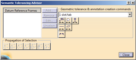
toolbar.The Semantic Tolerancing Advisor dialog box is displayed. 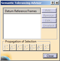
-
Select the median 3/4 circle arc which symbolizes the thread helical surface.
The Semantic Tolerancing Advisor dialog box is updated according to the selected element. 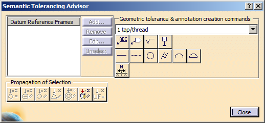
ThePropagation of Selection options are displayed according to the type of face selected depending on the canonicity. In this scenario the options are not used.
The All same diameter, same pitch, parallel CG thread Cylinders
 option is available. This option allows you to propagate the
selection to the threads in the 3D part with the same diameter
and pitch, and parallel axis with the selected Constructed Geometry
Thread.
option is available. This option allows you to propagate the
selection to the threads in the 3D part with the same diameter
and pitch, and parallel axis with the selected Constructed Geometry
Thread.Click this option if you want to select all the threads.
For more information, refer to Propagating Geometry Selection for Feature Creation.
-
Click Thread Diameter (One tap/thread):

The thread diameter dimension is previewed and the Limit of Size Definition dialog box is displayed, offering the following options:
-
Pitch: lets you display the pitch value in the thread dimension.
-
Tol class: lets you define and display the tolerance class value in the thread dimension.
-
-
Select the Tol class option and in the Tol class drop-down list, select 6g as the tolerance class value.
The pitch value is defined according to the selected standard when you created the thread. 
-
Click OK then anywhere in the geometry window to unselect.
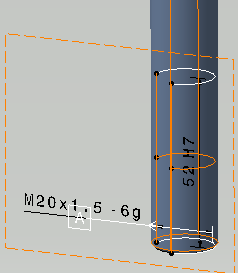
The thread diameter dimension is created.
The M symbol is displayed instead of the diameter symbol according to the selected standard when you created the thread.
If no standard has been defined the diameter symbol is displayed. -
Back in the Semantic Tolerancing Advisor dialog box, multi-select (using the Ctrl key, for example) the 3/4 circle arcs which symbolize the thread starting and ending planes.
Note that the 3/4 circle arcs which symbolize the thread starting and ending planes are recognized as planar surfaces, which means that you can tolerance them just like any other planar surface. -
Once again, the Semantic Tolerancing Advisor dialog box is updated according to the selected elements.
-
Click Distance Creation (1 slot/tab):

The thread length dimension is previewed and the Limit of Size Definition dialog box is displayed, offering the following options: - General Tolerance: lets you define a pre-defined class of tolerance, see Tolerances for the default class setting.
- Numerical
values: lets you define the Upper Limit and optionally the
Lower Limit (provided you uncheck the Symmetric Lower Limit
option).
If the Propose the last created tolerance values check box is selected in Tools > Options > Mechanical > Functional & Tolerancing Annotations, Tolerances tab, New Size Tolerances Creation area, the last tolerance type and values defined for Numerical values in the previous command are proposed as default for the next command. - Tabulated values: lets you define fitting tolerances. Refer to Normative References for more information: ISO 286, ANSI B4.2.
- Single limit: lets you enter a minimum or maximum tolerance value. Use the Delta / nominal field to enter a value in relation to the nominal diameter value. For example, if the nominal diameter value is 10 and if you enter 1, then the tolerance value will be 11.
- Information/Reference: lets you to set the dimension as information (ISO-based standards)/ reference (ASME-based standards). The information/reference dimension is displayed enclosed by parentheses in geometry window.
-
Select the Tabulated values option.
-
Click OK then anywhere in the geometry window to unselect.
-
Click Close in the Semantic Tolerancing Advisor dialog box.
The thread dimensions and tolerances are displayed in the geometry as well as in the specification tree. 

-
Click Tolerancing Advisor
in the
Annotations
toolbar.The Semantic Tolerancing Advisor dialog box is displayed. -
Select the median 3/4 circle arc which symbolizes the thread helical surface.
The Semantic Tolerancing Advisor dialog box is updated according to the selected element. -
Click Datum Feature (1 tap/thread):

The Datum Definition dialog box appears and the datum is created.
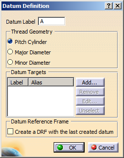
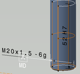
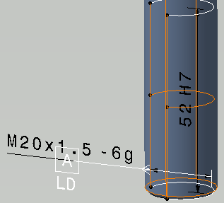
By default, Pitch Cylinder option is selected. It is applied on the axis of the pitch cylinder. -
Select Major Diameter or Minor Diameter option as per your requirement.
- Major Diameter: it is applied on the major diameter of the thread.
- Minor Diameter: it is applied on the minor
diameter of the thread.
-
Click Close in the Semantic Tolerancing Advisor dialog box.
The datum target is created and displayed in the geometry, as well as in the specification tree.