- The same sphere surface.
- The same plane surface.
- The same cylinder surface.
- The same cone surface.
- The same torus surface.
- A pattern of parallel cylinders.
- A pattern of spheres.
To improve the highlight of the related geometry, see Highlighting of the Related Geometry for 3D Annotation.
-
Select the cylindrical hole as shown.
-
Click Tolerancing Advisor
 in
Annotations toolbar.
in
Annotations toolbar.
The Semantic Tolerancing Advisor dialog box appears. The geometry propagation selection commands are available.

The options are activated according to the type of face selected depending on the canonicity. In this case as the cylindrical face is selected we have two options out of the three available options activated:
-
Select the All same diameter parallel cylinder option. You can see that all the cylindrical surfaces are highlighted.
-
Click Position Specification
 in the dialog box.
The Geometric Tolerance dialog box appears. Click OK.
The specification is created.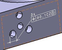
Click Close in the Semantic Tolerancing Advisor dialog box to end the command.
-
Select the spherical hole.
- Click
Text with Leader
 in the
Annotations
toolbar (Text
sub-toolbar).
in the
Annotations
toolbar (Text
sub-toolbar).
The Tools Palette for geometry propagation is also displayed.The Text Editor dialog box appears. 

There are two options in the Tools Palette: - All same canonicity faces
- All same diameter parallel sphere
- You can also select additional faces if required.
The Tools Palette is displayed according to the type of face selected depending on the canonicity. -
In this case, select the All same diameter parallel sphere option. You can see that all the spherical surfaces are highlighted.
-
Enter the text, for example All Spherical Faces in the dialog box.
Click OK to end the text creation. You can click anywhere in the geometry area too.
The text is commonly created for all the faces. 
Using the All same canonicity faces option
To improve the highlight of the related geometry, see Highlighting of the Related Geometry for 3D Annotation.
- Select the planar
surface as shown.
- Click
Flag Note with Leader
 in
Annotations
toolbar (Flag
Note
sub-toolbar).
in
Annotations
toolbar (Flag
Note
sub-toolbar).
The Tools Palette for geometry propagation is also displayed.The Flag Note Definition dialog box appears. 

There is only one option in the Tools Palette: - All same canonicity faces
- You can also select additional faces if required.
-
Select the All same canonicity faces option. You can see that all the planar surfaces are highlighted.
-
Enter the flag note's name as Geometry Propagation in the Name field.
Click OK.
The flag note is created for all the faces commonly. 
- Constructed Geometry Creation

- Text with Leader
,
Text
 ,
Text Parallel to Screen
,
Text Parallel to Screen

- Flag Note with Leader
,
Flag Note

- Datum Element

- Datum Target

- Geometrical Tolerance

- Surface Texture

- Tolerancing Advisor