 |
| This page deals with the options concerning:
|
New Size Tolerances Creation
|
 |
Propose the last created tolerance values
|
|
Defines whether the last tolerance type and values defined in a command
should be proposed as default for the next command in
the Limit of Size Definition dialog box
available via Tolerancing Advisor. |
 By default, this option is not selected.
 |
 |
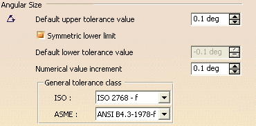
Angular Size
|
 |
| Defines the angular size options: |
Default upper tolerance value
|
| Defines the default upper tolerance value for angular size. |
 By default, the upper tolerance is 0.1deg.
 |
Symmetric lower limit
|
| Defines whether the default lower tolerance value is
symmetric in relation to the default upper tolerance value. |
 By default, this option is selected.
 |
Default lower tolerance value
|
| Defines the default lower tolerance value for angular size,
enable when Symmetric
lower limit is not selected. |
 By default, the lower tolerance is -0.1deg.
 |
Numerical value increment
|
| Defines the increment for angular size numerical value. |
 By default, the increment is 0.1deg.
 |
General tolerance class
|
Defines the general tolerance class for angular size,
according to the standard of annotation set.
 |
- If the standard of annotation set is ASME or ANSI, then ASME general
tolerance class value will be considered, else ISO tolerance class value
will be considered.
- Based on the selected conventional
standard, customized tolerances (ISO, ANSI-ASME, or JIS) appear
in the General Tolerance list in the Limit of
Size Definition dialog box.
|
|
 By default, the general tolerance class for ISO is ISO 2768 - f.
 |
 By default, the general tolerance class for ASME is ANSI B4.3-1978-f.
 |
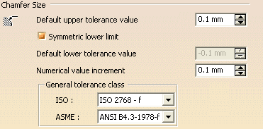
Chamfer Size
|
 |
|
Defines the chamfer tolerance options: |
Default upper tolerance value
|
|
Defines the default upper tolerance value for chamfer size. |
 By default, the upper tolerance is 0.1 mm.
 |
Symmetric lower limit
|
|
Defines whether the default lower tolerance value is symmetric in
relation to the default upper tolerance value. |
 By default, this option is selected.
 |
Default lower tolerance value
|
| Defines the default lower tolerance value for
chamfer size, and is
enabled when
Symmetric
lower limit is not selected. |
 By default, the lower tolerance is -0.1 mm.
 |
Numerical value increment
|
| Defines the increment for chamfer size numerical
value. |
 By default, the increment is 0.1 mm.
 |
General tolerance class
|
Defines the general tolerance class for chamfer
size, according to the standard of annotation set.
Note: If the standard of annotation set is ASME or ANSI, then ASME general
tolerance class value will be considered, else ISO tolerance class value
will be considered. |
 By default, the general tolerance class for ISO is ISO 2768 - f.
 |
  By default, the general tolerance class for ASME is ANSI
B4.3-1978-f.
 |
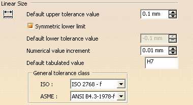
Linear Size
|
 |
| Defines the linear size options: |
Default upper tolerance value
|
| Defines the default upper tolerance value for linear size. |
 By default, the upper tolerance is 0.1mm.
 |
Symmetric lower limit
|
| Defines whether the default lower tolerance value is
symmetric in relation to the default upper tolerance value. |
 By default, this option is selected.
 |
Default lower tolerance value
|
| Defines the default lower tolerance value for linear size,
enable when Symmetric
lower limit is not selected. |
 By default, the lower tolerance is -0.1mm.
 |
Numerical value increment
|
| Defines the increment for linear size numerical value. |
 By default, the increment is 0.01mm.
 |
Default tabulated value
|
| Defines the default tabulated for linear size.
While creating dimensions, upper case
and lower case letters of tabulated values appear based on the selected
element, hole or shaft. |
 By default, the tabulated value is H7.
 |
General tolerance class
|
Defines the general tolerance class for linear size,
according to the standard of annotation set.
Note: If the standard of annotation set is ASME or ANSI, then ASME general
tolerance class value will be considered, else ISO tolerance class value
will be considered. |
 By default, the general tolerance class for ISO is ISO 2768 - f.
 |
  By default, the general tolerance class for ASME is ANSI B4.3-1978-f.
 |
Geometrical Tolerance, Datum
Target and Datum System
Defines the default numerical values for geometrical tolerance and datum
target.
|
Description
|
| Lets you specify the description of the numeric display.
Based on the unit specified in the Description list, the values are
displayed for datum targets and semantic geometrical tolerances. |
 By default, NUM.DIMM is selected.
 |
Display
|
| Lets you specify the number of units in which the values
needs to be displayed. |
For example, if you select FEET-INC
in the Description list, based on the number of units selected in the
Display list, the numerical values will appear as below:
- 1 factor: Numerical values will
be displayed in feet only.
- 2 factor: Numerical values will be displayed in
feet and inch.
|
|
Precision
|
| Defines the geometrical tolerance and datum target precisions after the
numerical separator. |
 By default, the precision is 0.01.
 |
Separator
|
| Defines the geometrical tolerance and datum target symbols used as numerical
separator. |
 By default, the separator is a dot ".".
 |
Default numerical value
|
| Defines the default numerical for geometrical tolerance. |
 By default, the numerical value is 0.1mm.
 |
Numerical value increment
|
| Defines the increment for the geometrical tolerance and
datum target
numerical values. |
 By default, the numerical increment value is 0.01mm.
 |
Display trailing zeros
|
| Defines whether "0"s complete the number of digit displayed
after the separator, according to the precision. |
 By default, this option is not selected.
 |
Display leading zero
|
| Defines whether the "0" before the numerical separator,
when value is less than 1, is displayed. |
 By default, this option is selected.
 |
 |


