- When defining a datum on planar or cylindrical surfaces the use of datum targets is optional.
- A target element can be a point, line, circular or rectangular surface
lying on the datum element:
- When the datum target is a point, then the circular frame is linked to a cross-placed on the surface. Framed dimensions shall define the location of the point.
- When the datum target is a line, then the circular frame is linked to a line placed on the surface. Framed dimensions shall define the length and the location of the line.
- When the datum target area is square or circular, the area dimensions are indicated in the upper compartment of the circular frame, or placed outside and connected to the appropriate compartment by a leader line (when there is no sufficient space within the compartment).
-
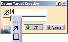
If the datum target is created on a point geometry then you can specify the form (point, circle and rectangle) and the size of the limited zone. Otherwise the options are disabled.
- The minimum number of targets is defined by the datum depending on whether it is used as primary, secondary or tertiary datum in a reference frame.
- For instance, if the datum feature is a cylinder, the targets may be two non-parallel lines, tangent to the cylinder and perpendicular to its centerline, in order to define "equalizing" datum ("V-type-equalizers").
- If the datum element is prismatic or complex, the use of datum targets is mandatory. In this case when selecting targets a message indicates the current step of the datum definition.
- When the datum is established from datum targets, then the letter identifying the surface is repeated on the right side of the datum indicator followed by the list of numbers identifying the targets (separated by comas).
- When there is no sufficient space within the compartment, the dimensions of the datum target area are placed outside the circular frame and connected to the appropriate compartment by a leader line terminated by a dot.
- Improve the highlight of the related geometry, see Highlighting of the Related Geometry for 3D Annotation.
-
Activate the Front View.1 annotation plane.
-
Click Datum Target
 in
Annotations toolbar.
in
Annotations toolbar.
-
Select the face as shown (It is defined as datum plane D).
The Datum Target Creation dialog box appears. 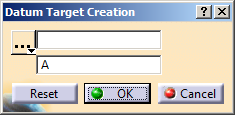

The Tools Palette is displayed according to the type of face selected depending on the canonicity. In this scenario the Tools Palette is not used. For more information, refer to Propagating Geometry Selection for Feature Creation.
-
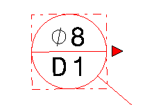
Select the area of contact symbol from the list in the Datum Target Creation dialog box, enter 8 in the field opposite to the list, and enter D1 in the remaining field.
-
Select the Movable check box in the Datum Target Creation dialog box and then a geometrical element in the Direction box to create a movable datum target feature.
Optionally, click the red arrow next to the datum target.
- You can select any of the following geometrical elements:
- Edge
- Line
- Plane
- Planar face or surface
- Based on the selected direction element, the beak of the movable
datum target annotation is oriented as below:
- Along the line if you select a line or edge coplanar with the view in which the datum target is created.
- Along the normal to the plane if you select a plane, planar face or surface which is not coplanar with the view in which the datum target is created.
- The beak of the movable datum target gets default orientation if the direction of the movement is not coplanar with its view.
The datum target is now movable.
-
Click OK to validate.
You have created a datum target on datum plane D. Its name is "D1" and it is identified as "Datum Target.xxx" in the specification tree. 
-
For the selected datum target annotation and the datum systems, to modify the numerical display properties specified under Geometrical Tolerance, Datum Target, and Datum System in the Tools > Options > Mechanical Design > Functional Tolerancing & Annotation > Tolerancing tab:
- Right-click the datum target annotation and select Properties.
- In the Properties dialog box, click the Numerical Display tab.
- Under Numerical Display and Format, modify the required options.
For more information, see Geometrical Tolerance, Datum Target, and Datum System.
The datum target annotations are displayed according to the modified display properties
-
-