The integration with Generative View Styles allows you to store the drawing options such as those described below in the drawing document and no longer in the Flattening Parameters:
- Type of representation for bundle segments, mechanical parts
and protective coverings:
- Double line
- Single line, with the possibility of having the line type sized to represent the various layers in overlapping protective coverings
- Graphic replacement for devices, supports, support sections
and ends of protective
coverings:
- 3D projection
- 2D detail. 2D details for supports and ends of protective coverings are automatically oriented. A GVS parameter lets you orient 2D details for devices. A GVS parameter also lets you size 2D details to represent the various layers in overlapping protective coverings. 2D details showing support section views are automatically generated as defined by GVS parameters.
Note that GVS only works on Electrical Harness Flattening data, that is to say after extraction from the 3D data.
For more information on dedicated GVS parameters, see Electrical Harness Flattening Parameters; for more general information, see the Generative View Style section.
To obtain a default front view drawing or automatic generation of text templates:
-
Copy the sample GVS file, Electrical_DefaultGenerative.xml, from intel_a \ resources \ standard \ generativeparameters \ SAMPLES to intel_a \ resources \ standard \ generativeparameters
-
Run the Front View or Automatic Generation command and select the
sample GVS file just copied.

For this to work correctly, you must not identify the catalog path and name in the Tools > Options > Electrical Harness Flattening > General tab. This is a simple method allowing you to generate a complete electrical drawing without having to customize the drafting environment.
![]()
Location of Generative View Style Files
The location of generative view style files is defined by an environment variable, which can be set during installation or modified afterwards:
|
Variable name |
Description |
CATCollectionStandard |
Path and
name of the folder which contains:
|
Copy the
.../online/ehfug_C2/samples/standard/generativeparameters/GVS_sample_1.xml
to the respective folder in your environment.
Refer to the Generative Drafting User's Guide for Administration Tasks.
Set up the Drafting > Administration option as follows:
Refer to the Administration tab documentation.
-
Open the Tools > Options... menu, then in the Equipment & Systems > Electrical Harness Discipline category, select Electrical Harness Flattening to define the electrical drawing catalog for devices, supports and ends of protective coverings.
To do so: -
Click Add
-
Browse to the catalog:
.../online/ehfug_C2/samples/GraphicReplacement/CATDraw2DElectricalDetail.catalog. -
Click OK to validate.
This catalog contains the 2D details for devices, supports and ends of protective coverings.
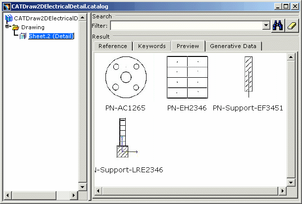
2D Details for Ends of Protective Coverings
The same 2D detail is used for both ends of the protective covering. This is why, when defining the detail, the administrator must respect detail symmetry about the x-axis.
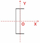
The center of the detail is placed on the end point of the protective covering and the OX axis of the detail follows the tangency of the curve at the previous point.
When generating the drawing, 2D details are sized according the layer of protective covering to which they are applied.
To take the 2D detail into account, the user must set the attribute, External reference, to the name of the catalog detail. To do so:
- Right-click the instantiated protective covering and select Properties from the contextual menu.
- Click More... in the Properties dialog box that opens.
- Select the Electrical tab and enter the name of the 2D detail in the drawing catalog in the External Reference field.
- Click OK when done.
Also refer to Using Different Line Types and 2D Details for Overlapping Protective Coverings.
2D Details for Support Section Views
By default, one 2D detail per support section will be generated. Details are positioned on the drawing on a grid. Details of support sections are oriented according to the orientation of the support in the 3D view.
Supports are identified by a letter and corresponding details are identified using the same identifier plus a prefix, if desired.
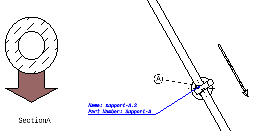
For more information about:
- The various GVS parameters you can set, see Electrical Harness Flattening Parameters.
- Customizing the support balloon style, see Interactive Drafting: Administration Tasks: Setting Standard Parameters and Styles: Setting Standard Parameters: Annotation Styles.
-
-
Open the Tools > Standards... menu.
The Standard Definition dialog box opens. - Select generativeparameters in the Category list.
-
Select GVS_sample_1.xml in the File list.
The electrical components shows with their representation: 
For example, the graphic representation is:
- Single line for bundle segments
- Double line for protective coverings
- 2D detail from the previously defined catalog for
single insert connectors


About Splices
It is possible to define a graphic replacement for the splices in the GVS, either 2D detail or 3D projection.
However, only the 2D detail is valid, as the 3D representation, displayed like this:
cannot be projected in the drawing.
If you select this generative view style to generate a Front View drawing
 :
:
the drawing looks like this: 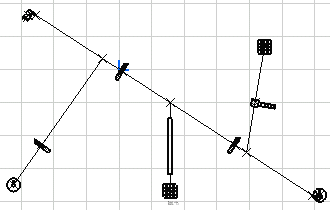
-
In the Standard Definition dialog box, now select the DefaultGenerativeStyle.xml in the File list.
The electrical components shows with their representation: 
For example, the graphic representation for the bundle segment is in double line, etc.
If you select this generative view style to generate a Front View drawing
 :
:
the drawing looks like this: 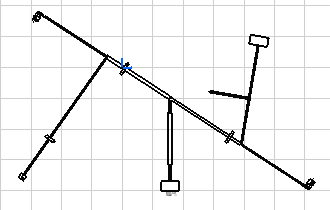
About Protective Coverings
To take into account the different line types for as well as the 2D details on ends of protective coverings, the administrator must set generative view style parameters as follows for both tape and corrugated tube.
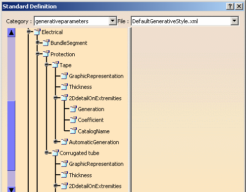
- GraphicRepresentation: set to SingleLine. By default, this parameter is set to DoubleLine.
- Thickness: set to Yes. This parameter lets you take
into account the customized line type
standard and ensures that the appropriate line type is assigned
to the different layers of overlapping protective covering.
By default, Thickness is set to No.
Three GVS parameters (under a 2DdetailOnExtremities node) let you manage 2D details on the ends of protective coverings:
- Generation: enter Yes to use the 2D detail. By default, Generation is set to No.
- Coefficient: enter an integer. This lets you define a coefficient that sizes the 2D detail according to the layer of protective covering, so that 2D details on different layers are clearly visible. By default, Coefficient is set to 1.1 and the 2D detail is 110% bigger with each layer.
- CatalogName: enter a string. This is the name of the catalog containing the 2D detail. The catalog is the one identified as the electrical drawing catalog (Tools > Options > Equipment & Systems > Electrical Harness Discipline > Electrical Harness Flattening). If no catalog is specified, the system scans all catalogs defined in Tools > Options.
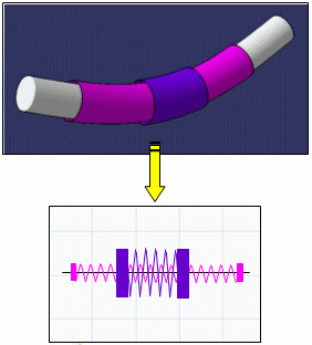
Also refer to Using Different Line Types and 2D Details for Overlapping Protective Coverings. Orienting 2D Details for Devices
2D details for devices can be oriented:
- With respect to the XOY axis of main drawing view (default orientation), or
- To match bundle segment tangency.
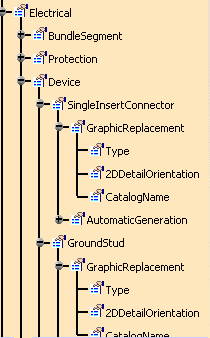
This is managed via GVS parameter 2DDetailOrientation located under the GraphicReplacement node of each device entry.
By default, 2DDetailOrientation is set to No and the local XOY axis of the 2D detail is oriented with respect to the XOY axis of main drawing view.
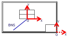
Setting 2DDetailOrientation to Yes orients the OY axis of the 2D detail to match bundle segment (BNS) tangency.

-
Click OK to exit the Standard Definition window when you are done.
GVS and User Mode
Note that you can change the characteristics of a given GVS only if you are working in administration mode.
In user mode, however, you can:
A. Apply a GVS to a view:
- Right-click the active view and select Properties from the contextual menu.
At the bottom of the Properties dialog box, the Generative view style list box lets you select the style of interest:
- Or, right-click the active view and select View object > Generative View Style > Set View Style from the contextual menu.
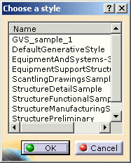
The Choose a style dialog box opens, letting you select the style of interest.
B. Apply the GVS of one view to another view:
- Right-click the first view
- Select View object > Generative View Style > Apply View Style To from the contextual menu
- Click the view to which to apply it.
C. Import a GVS into a drawing document. You may want to do this for one of two reasons:
- You want to import a new version of a GVS that already exists in the drawing document and is used in one or more views in order to update these views with the latest GVS parameters.
- You want to import a GVS that does not already exist in the drawing document in order to use it subsequently.
To import a GVS, select Tools > Import a generative view style...
The dialog box opens: Select a style and click OK to validate.

