- This task shows you how to use the definition of
variable cores (contour and height) to elevate a top
surface or a solid created from iso-thickness areas.
You select a top surface, or a solid and indicate a surface acting as top surface. - The Elevate Solid or Top Surface command retrieves the contours used in the definition of the variable cores found either in the complete stacking, or in a selection of plies.
- These contours are transferred from the surface supporting the plies and the variable core to the top surface you have selected.
- An offset of the value of the height of the variable
core is applied to this top surface to elevate it.
This offset top surface is then turned into a solid if the support was a solid.
![]()
- Available in Composites Engineering Design (CPE) and Composites Design for Manufacturing (CPM).
- The variable cores must have been defined as described in Creating a Variable Core.
- The elevation cannot be computed from overlapping or intersecting variables cores.
- The elevation may fail in some cases, e.g. when the variable cores lie on top surface discontinuities.
- The resulting top surface or solid will not be continuous in tangency.
Elevate Top Surface
-
Click Elevate Solid or Top Surface
 in the Top Surface & solid
toolbar.
in the Top Surface & solid
toolbar.
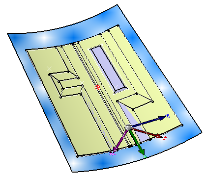
Select Area Top Surface.1.
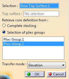
-
Choose Selection of plies groups and select Plies Group.2 to retrieve the core definition.
-
Define the Transfer mode.
- Projection: The projection is perpendicular to the top surface,
- Elevation: The projection is perpendicular to the surface supporting the plies.
Those modes are similar to those described in Skin Swapping.
We have selected Elevation. -
Click OK to validate and exit the dialog box.
The elevated top surface is created as a datum
under AddVariableCoreSet.
Elevate Solid or Top Surface elevates cores and deduces the top skin of the variable core.
The cores skin is somehow sewn on the original top surface.
Elevate Solid
-
Click Elevate Solid or Top Surface
in the Top Surface & solid
toolbar.
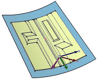
Select Solid from Iso-Thickness Area and Area Top Surface.1.
The top surface is required to define the level of elevation.
However it is not necessarily the top skin of the solid, as long as the elevevated cores can be added to the solid by a Boolean operation.
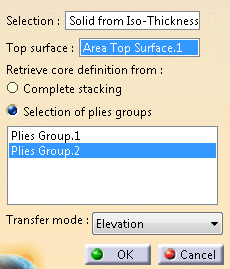
-
Choose Selection of plies groups and select Plies Group.2 to retrieve the core definition.
-
Define the Transfer mode.
- Projection: The projection is perpendicular to the top surface,
- Elevation: The projection is perpendicular to the surface supporting the plies.
Those modes are similar to those described in Skin Swapping.
We have selected Elevation. -
Click OK to validate and exit the dialog box.
The elevated solid is created as a datum,
under AddVariableCoreBody.
![]()