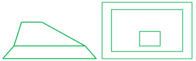
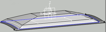
A variable core is an insert with this kind of shape (side and top view):
The following cases are not supported:
- Intersecting contours:
- Contour
without vertices, such as this inner contour:

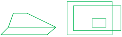
- Top contour not contain in
lower contour:
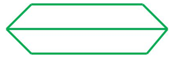
Basically, a variable core is defined by several contours
with a distance between those contours.
The first contour is the base of the
insert, the last contour is at the top, and intermediate contours are
positioned at slope changes.
All those contours lie on the reference
surface of the plies group where the variable core is created.
You can
create those contours with the Contour command.
The core can be defined either by the base contour, a height and an angle, or several contours and heights.
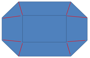
Cores with complex contours, i.e. with a different number of
vertices, require additional junction lines (shown in red below) to define
how the core looks like in the ramps.
Create a Variable Core from Contour, Height, and Angle
-
Click Core
 in the Plies toolbar and select a stacking..
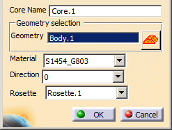
The Core definition dialog box is displayed.
-
In that dialog box, click
.
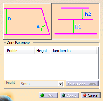
The Variable offset Core Creation dialog box opens.
-
Click the icon on the left.
The dialog box changes to:
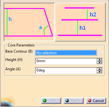
- Select the Base
Contour.
If required, use the contextual menu to create one. - Key in a Height.
- Key in an Angle.
- Select the Base
Contour.
-
Click OK to create the variable core and exit the dialog box.
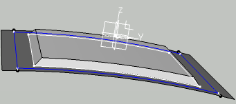
The Variable core is created after the Stacking, under Solid:CoreGeometry.
Create a Variable Core from Several Contours and Heights
Click Core
in the Plies toolbar and select a stacking..
The Core definition dialog box is displayed.
-
In that dialog box, click
.
The Variable offset Core Creation dialog box opens.
-
Click the icon on the right, and select the base contour.
As it is the base contour, leave its Height to 0.
Its name is displayed under Profile. -
Select the other contours.
Use the context menu item Remove to delete a contour. -
In the Height field that has become available, key in the required height.
The dialog box is updated, in particular, you are informed if junction lines are required or not. -
If required, click Edit Junction Lines.
- A new dialog box appears.
- Potential junction lines are displayed in the graphic area.
- A red traffic light is displayed at the start of the current contour. It turns green when all junction lines have been proposed for all vertices.
- Click the green traffic light to validate all proposed junction lines.
- Click the red traffic light to reset the definition of junction lines.
- Click the red check of a junction line in the 3D to delete one given junction line.
- Click the green check of a junction line in the 3D to validate a given junction line.
- Click Close when all junction lines have been defined to revert to the previous dialog box.
-
Repeat as often as necessary.
-
Click OK to create the variable core and exit the dialog box.
The Variable core is created after the Stacking, under Solid:CoreGeometry.
Create a Variable Core from Contours and Heights with a 90° Wall
The 90° angle is defined by selecting the
same contour twice.
There is no sample for this task, only images.
Click Core
in the Plies toolbar and select a stacking..
The Core definition dialog box is displayed.-
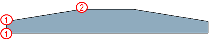
To create a variable core with a 90° wall, select the same contour twice:
- Select the base contour (1) and leave the height to 0.
- Select the same contour again, and enter the Height h1.
- Select the base contour (2) and leave the height to 0.
- Select the same contour again, and enter the Height h2.
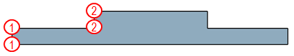
Adapt the contour selection to the requried geometry, for example
- For
Select the contour 1 (no height), contour 1 again with h1, contour 2 once with h2. - For
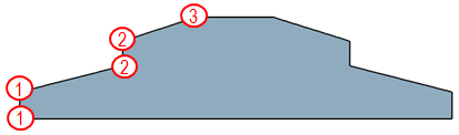
Select the contour 1 (no height), contour 1 again with h1, contour 2 with h2, contour 2 again with h3, finally contour 3 with h4.
- For
![]()