- Creating the Solid with Junction Lines (recommended),
- Creating the Solid with Ramp Contours (optional),
Creating the Solid with Junction Lines
-
Click Solid From Iso-Thickness Areas
 in the Top Surface & Solid toolbar.
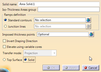
The Solid from Iso-thickness Areas dialog box is displayed.
Select Solid. The name of the solid is proposed. You can edit it.
-
Select a group of iso-thickness areas.
-
Select the Junction lines option and select those junction lines in the 3D viewer
or from the specification tree.
Multi-selection is available. -
If variable cores created as described in Creating a Variable Core exist, select the Elevate using variable cores check box and define a transfer mode.
The resulting solid or top surface will be elevated as explained in Taking Variable Cores into Account in Solids or Top Sufaces. -
Click Apply. The solid is computed.
-
Click OK to validate and exit the dialog box.
The solid is created:
If this kind of error is detected, create an ITP with the
point shown by the arrow as input.
Warnings are displayed when gaps or sharp edges are detected.
Creating the Solid with Ramp Contours (Optional)
-
Make Ramp the Define In Work Object.
-
Click Contour
 .
.
The Contour dialog box is displayed:
-
Select MOLD as the Surface.
-
Define a first ramp contour as shown below:
-
Click OK to validate and exit the dialog box.
-
Repeat those steps to define all the ramp contours as shown below:
-
Click Solid From Iso-Thickness Areas areas
.
The Solid from Iso-thickness Areas is displayed.
Select Solid. The name of the solid is proposed. You can edit it.
-
Select a group of iso-thickness areas.
-
Select the Standard contours option and select the contours you have just created.
Click Apply. The solid is computed and displayed. Click OK to validate and exit the dialog box.
Creating a Top Surface as OML
-
Select Top Surface and select required inputs.
-
Select the Invert Draping Direction check box.
The computed top surface represents the Outer Mold Line.
This check box is used mainly for plies generated with Master Stacking Sequence.
![]()