 |
This task shows you how to Add, Merge, Split and Edit cells
while defining the Grid.
Master stacking sequence mode is supported with no specific
behavior, except the display of warnings when a mix of laminates
(standard and defined from a master stacking sequence) is found, or when
a laminate is incompatible with the master stacking sequence. In this
case, the master stacking sequence and the layer data are not used
downstream. This may occur when importing laminates on cells or after a
manual edition of cells.
When importing grid data with a master stacking sequence, all the
columns of the first line columns must be completed by # (or a number).
Otherwise these columns will be ignored during the import.
See More about Materials and Laminates
for more information.
|
|
|
- This task is available in the CATIA Composites Engineering (CEG)
product.
- This task is available in the Composites Grid Design workbench.
|
 |
Either work on the part where you have defined the Grid Panel
or open the GridGA01.CATPart document. |
|
|
To define the laminate of the cell within the session, make sure you have
defined at least materials
as explained in Adding Materials
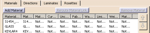
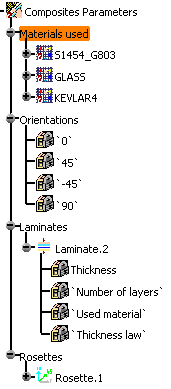
In GridGA01.CATPart, we have
defined three materials and one laminate.
You must have defined the Grid Panel.
You can access the Grid definition dialog box either:
- At its creation by clicking Grid
 and selecting a Grid Panel,
- Or by double-clicking an existing Grid or a cell of an
existing Grid.
- A warning is displayed if several structural elements have the same name.
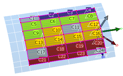
As soon as cells are displayed in the 3D viewer, you can select them.
- Multi-selection is available using the Ctrl key.
- If you select cells in the 3D viewer, the corresponding lines in the dialog box
are highlighted too.
- When you select rows in the dialog box, the corresponding cells are
highlighted in the 3D viewer.
- Once laminate information has been added, all the cells that share
the same laminate are displayed in the same color.
|
 |
-
Click Grid
in the Grid Design toolbar and select GridPanel.1
as the
Panel.
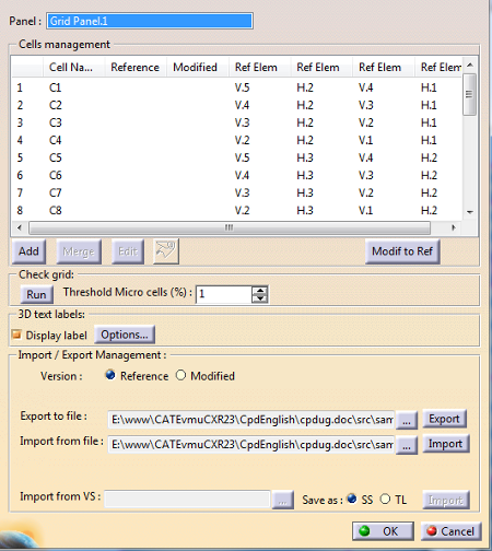
The Grid Definition dialog box is displayed.
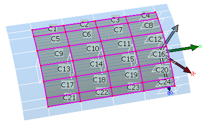
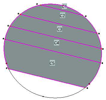
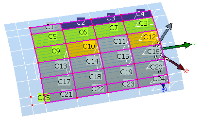
Cells are created from the grid panel you have defined and displayed
in the 3D viewer.
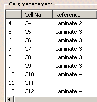
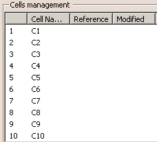
The dialog box is updated:
- The first column
gives the rank of the
item,
- The second column
gives the name of the
cell,
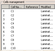
- In the
Reference or
Modified
column, SS or
TL
indicates whether a
stacking sequence
or a
thickness law has been
defined.
- The following
columns give the name of
the structural elements
that define each cell.
|
-
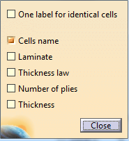
If required, select the Display label check
box and click Options.
In the dialog box that is displayed, you can select the information you
want to display on the cells.
-
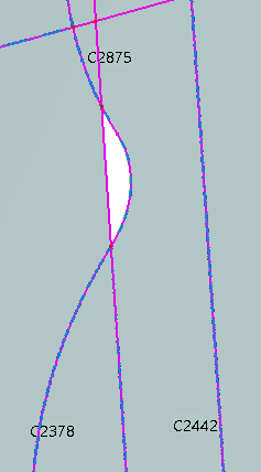
Check the
grid: Enter a threshold value for searching micro cells, and
click Run.
This check consists in finding:
- Geometrically
overlapping cells.
- Micro-cells, that
are cells with a surface
lower than the threshold
value.
This threshold is given
as a percentage of the
largest cell found in
the grid.
As this check is time consuming, it is
not done automatically.
However, we recommend that you run it at
the creation of the grid, or after a
modification of the structure of the
cells (add, split,...).
The result of the check appears in a
message. Detected cells are shown in the
graphic area. |
-
Once you are satisfied with the grid definition (see
steps below),
click OK to validate and exit the dialog box.
The grid is created in the specifications tree.
 |
Grid cells with two nodes as shown in the examples below are
not created.
 or or
 |
-
Double-click Grid Panel.1.
The Grid Definition dialog box is displayed.
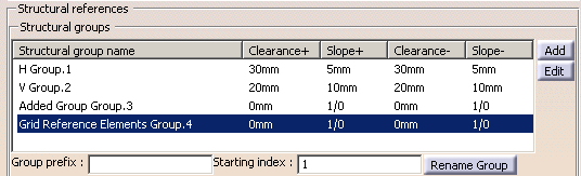
-
Highlight Added Group Group.3 in the dialog
box. Select Parallel.1 in the specification tree and click
Add.
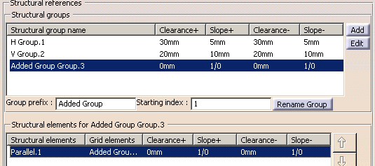
A Grid Reference Elements Group is added.
Click
OK to validate and exit the dialog box.
If necessary,
unhide Parallel.1.
-
Revert to the Grid definition dialog box.
Click Add in the dialog box.
A dialog box is
displayed.
-
Select the reference elements that form the contour of
the cell you want to add.
Once those reference elements form a closed contour, a green tip replaces the red cross.
-
Click OK. A message proposes you to edit the
new cell.
If you click Yes, go to Editing Cells.
If you click No, a new cell is added to the grid, but without
laminate information.
-
Select at least two cells, either in the dialog box or
in the 3D viewer.
Merge becomes available.
-
Click Merge. The cells are merged into a
single one.
Only manifold cells can be merged.
If the cells to merge do not have the same stacking sequence or the same
thickness law,
a message asks you to validate that the result cell will keep one of the
laminates
(the laminate with higher thickness is proposed).
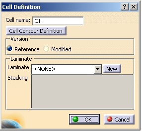
Edit lets you enter laminate information for a newly created cell or to
overload the existing laminate information.
-
Select one or several cells, either in the dialog box or
in the 3D viewer, and click Edit.
The cell definition dialog box is displayed.
-
If you have selected one single cell, you can edit its
name or its contour.
|
- The name must be
unique. If this is not
the case, the creation
is impossible and you
are invited to change
the name
- When you edit the
name:
- the
grid
definition
(dialog
box and
authoring
window)
is
updated
with
this new
name.
- If
it
already
exists,
the
virtual
stacking
(dialog
box and
authoring
window)
is
updated
with
this new
name.
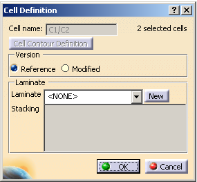
If you have selected several cells, their names and their contours are
not editable.
Only the number of selected cells is displayed.
|
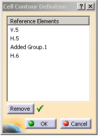
-
Click Cell contour definition.
Select the reference elements that will make the new contour.
Once this contour is valid, the red cross is replaced by a green check.
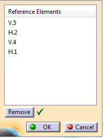
Click OK to validate and revert to the Cell definition dialog
box.
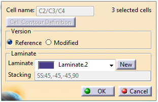
-
Choose which version of the cells you want to modify,
Reference or Modified.
If you have done modifications in one version before switching to the
other, a
message informs you that those modifications will be lost.
-
If you want to use a laminate already existing in your
design, select it from the Laminate list.
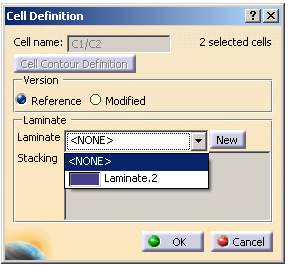
-
If you have not yet defined a laminate in your design,
or if you want to define a new one,
click New under Laminate.
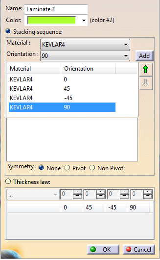
Define the laminate as explained in
Adding Laminates.
Click OK to validate and revert to the Cell Definition
dialog box.
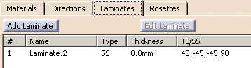
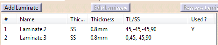
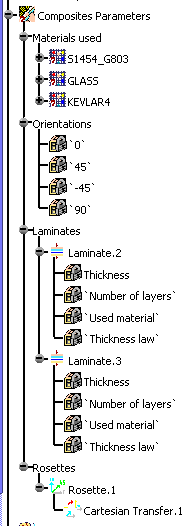
This newly created laminate is stored under Composites Parameters >
Laminates,
and appears in the Composites Parameters dialog box, in the
Laminates tab.
and in the specifications tree
-
If you want to apply the laminate from one cell to
others
- In the Grid
Definition dialog
box, select the cell
with the desired
laminate, and the other
cells.
- Click Edit.
- Select the required
laminate from the
Laminate list.
- Click OK. The
laminate is applied to
all the selected cells.
|
-
Repeat the steps above as necessary.
The dialog box is updated with the laminates information.
The cells are displayed in the 3D viewer with the color of their
laminate, when defined.
|
|
|
The .xls, .xlsx or .txt file must contain:
- A table with the cell IDs,
- The laminate name to apply to each
given cell,
- The list of the reference elements composing the contours of
the cells,
- The definition of each used laminate, with stacking defined
either as stacking sequence or thickness law.
-
Go to Import/export Management. -
Select the Version for which you want
to export or import data (Reference or Modified). -
In Export to file, click ...
and enter the path and name of the file where you want to export the
data.
In the File Selection box, select the format of that file (.xls,
.xlsx or .txt). -
Click Export to launch the export.
You can find examples of the export files in the Samples directory:
GridData.xls,
GridData.xlsx,
GridData.txt.
If all laminates are defined from a master stacking sequence, this
specific format is used. Otherwise, export is done in the standard
stacking sequence format, without layer key information. A warning is
displayed.
See More about Materials and Laminates
for more information. -
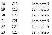
Modify the export file according to your needs.
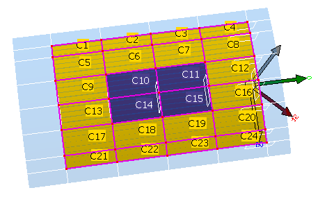
In GridDataModified.txt, we
have created a new laminate (Laminate.5) and applied it to Cells C18 to
C23. -
In Import from file, click ...
and enter the path and name of the file you want to import. -
Click Import to launch the import.
A message informs you of the result of the import.
The dialog box and the 3D viewer are updated with the imported
data.
Note that the new laminate is visible in the specifications tree, the
Cell definition dialog box
and the Composites Parameters
dialog box after you have clicked OK in the Grid
definition dialog box. |
 |
- The name of the structural elements contained in the imported file
must be the same as those used for defining the panel.
- If two reference elements cut each other twice, an warning message
is displayed.
|
|
|
Importing Data from the Virtual Stacking
When a Virtual Stacking has already been defined in your
design,
you can import its laminate information in the grid.
|
|
|
Open GridGA02.CATPart from the
samples directory. |
|
|
-
Double-click Grid.1.
-
Select the Version
for which you want to import the
data. We have selected Modified.
In Import from VS,
select how the laminate
information from the virtual
stacking will be saved in the
grid,
as a SS
(Stacking Sequence) or as a TL (Thickness Law). If several virtual stackings
exist, click ... and
select the one you need. Click Import. An information message is
displayed, the dialog box and
the cells in the 3D viewer are
updated.
The modifications are visible in
the Cell definition
dialog box once you have clicked
OK
in the Grid
definition dialog box.
Before the import:
After the import:
|
|
|
|
|
-
Select one or several cells to split, either in the
dialog box or in the 3D viewer.
-
Click Split and select the reference element that will
split the cells.
This reference element must intersect the cells only twice.
If this is not
the case, you have to perform the split in several steps, each complying
with this rule.
-
The cells are split.
|
|
 |