This is useful when, as a design engineer, you have defined a butt splice zone or a no splice zone
that does not take into account the manufacturing tolerance; or when you need to rework a butt splice zone
or a no splice zone after having synchronized the Engineering and the Manufacturing parts.
- Gap Offset:
- Creates the offset curves that take the manufacturing tolerance into account,
- Deletes the current butt splice zone or no splice zone,
- Recreates the butt splice zone or no splice zone from the offset curves,
- Keeps the associativity.
-
Click Gap Offset
 in the Splicing toolbar.
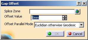
The Gap Offset dialog box is displayed.
-
Select the butt splice zones or no splice zone to process.
Multi-selection is available.
The Gap Offset will be applied to the whole selection. -
Key in the value of the curves offset.
-
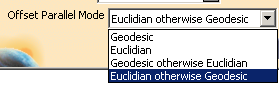
Select an Offset Parallel Mode from the list:
-
Click OK. All the selected splice zones are extended by the value of the offset defined.
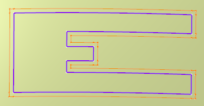
In our example below: - We have selected the butt splice zone corresponding to the purple contour (Contour.5).
- At OK, the Contour.5 is hidden.
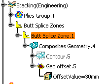
- Tthe offset (30mm) is applied to the curves of Contour.5.
- A new butt splice contour (Gap offset.5 shown in orange) is created from the offset curves.
-
If required, double-click a Gap offset.x to edit it.
Only Offset Value and Offset Parallel Mode are proposed in the dialog box that appears.
![]()