Important: You must have already generated the in-process model (IPM). Otherwise, you will not be able to extract fabrication sketches and you will get a warning message. .
Extract a Fabrication Sketch
-
Click Workshop Documents Extraction
 .
.The Workshop Documents Extraction dialog box appears. -
In the PPR tree, select the initial marking and cutting activity of the shape for which you want to generate a fabrication sketch.
Selected activity is listed in the top half of the dialog box. The possible workshop document extractions for this activity:
- profile fabrication sketch
- XML data for profiles
Note: IBC data is proposed for for curved profiles only.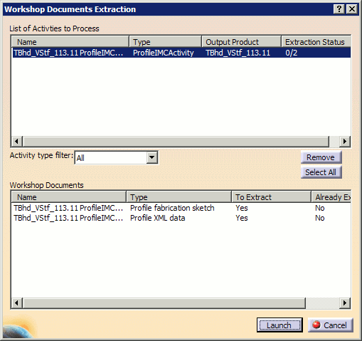
-
Set To Extract to Yes for the Profile fabrication sketch.
-
Click Launch when done.
The drawing is generated and saved in the location identified in the Project Resource Management (PRM) file (by default, workshop documents are saved in C:\temp, see Managing Project Resources).An Information box appears summarizing the process and indicating how successful or not it has been.
-
Click No to continue.
-
Open the CATDrawing generated using File -> Open.
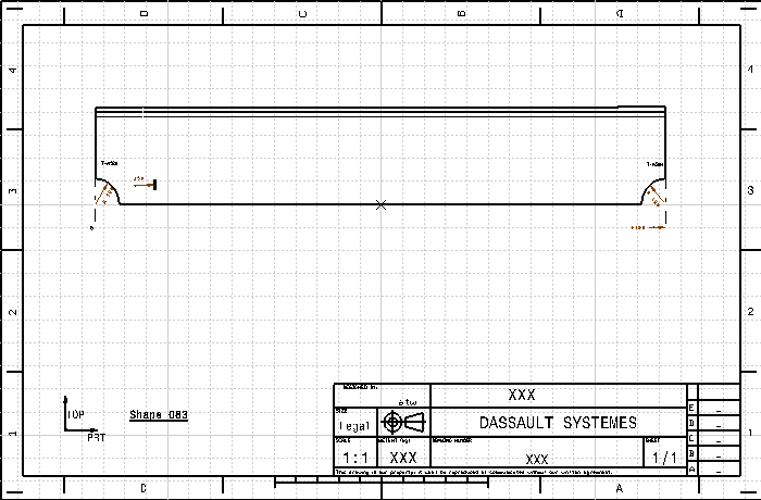
Note: The CATDrawing has a frame and title block (taken from the template drawing). You should also note the ship orientation and the part name.

To find out more about the symbols and dimensions are used on profile/shape fabrication sketches, see Setting Up the Symbols Catalog.
Extracting Profile XML data
Profile XML data documents are generated in the same manner as described above, with the exception that you must ensure that To Extract is set to Yes for the Profile XML data in Step 3.
A Profile XML data document represents all of the attributes (piece part and fabrication of the part) related to shape manufacturing data in XML format. These attributes include:
- General
- Date
- Time
- User
- Object
- ID
- Description
- Timestamp
- Revision
- Quantity
- Part
- FunctionalDescription
- abstransform
- Material
- Grade
- MaterialDensity
- XplusDirectionName
- XminusDirectionName
- YplusDirectionName
- YminusDirectionName
- ZplusDirectionName
- ZminusDirectionName
- Weight
- centreOfGravity
- Marking
- type
- side
- geometryMarking
- GeometryType
- Curve
- LineType
- Profile
- CrossSectionType
- CrossSectionParam
- WebHeight
- WebThickness
- FlangeWidth
- FlangeThickness
- LeftExcess
- RightExcess
- CuttingLength
Profile XML Data Appearance
When viewed, the extracted XML file has the following appearance.
|
|
The format of the following example is based on the style sheet provided with your V5 installation. This style sheet may be customized or replaced to view the same data in a different format. If you wish to use your own XML style file, you can edit the workshop document style file (WorkshopDocuments_Style.xml) to indicate that your desired style file is used. |
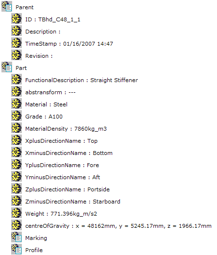
Nodes can be expanded and collapsed by clicking
either the
![]() icon or the topic text. As an example, clicking
the Parent and Part nodes reveals additional
information on those topics:
icon or the topic text. As an example, clicking
the Parent and Part nodes reveals additional
information on those topics: