It is the administrator's job to set up the shipyard's dedicated catalog of symbols that represent the following IPM part features: slots, endcuts, cutouts, alignment lines and margins. Also, document definition points can be modified as needed. When doing so, the following rules must be respected to ensure that symbols are correctly identified.
Endcuts, Slots and Cutouts
-
Open the following catalog:
..\OS\startup\EquipmentAndSystems\Structure\DetailingFeatures\FeatureCatalog\Parametric\DetailingFeatures.catalog -
Open the ConnectionDetails\Endcuts\Tee\StandardEndcut chapter.
This catalog contains some useful 3D user features that you will be able to apply to a shape.
-
Open the catalog of 2D symbols:
..\OS\startup\EquipmentAndSystems\Manufacturing\DrawingSymbols\ProfileFabricationSketch_2DSymbols.catalog s
sThis sample catalog contains a few commonly used profile families, and if you come across a profile whose family is different from those provided, customize the catalog by creating chapter with the same name as that of FamilyName of the profile.
-
Copy and then paste the chapter you want to customize, then rename so that its name corresponds to the FamilyName of the profile.
Once you have done this, you can begin to preview the chapters.
This catalog contains two chapters for endcuts: T-A58H and T-A49XH. These chapters correspond to 3D user features defined in the first catalog.
-
Select the T-A49XH chapter and click the Preview tab.
This chapter contains two components, T-A49XH_Start and T-A49XH_End, representing the symbols for start and end endcuts. The naming rule will ensure the correct mapping between the 3D endcut and the 2D symbol.
Alignment Lines and Margins
-
Select the AlignmentLines chapter and click the Preview tab.
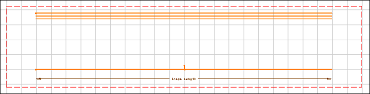
This chapter contains two symbols, one for the start and one for the end of the alignment line. The alignment line is represented by a straight line. The symbol also contains a dimension (Dim) whose value is the offset defined for alignment lines in the joining activity.
The administrator can define several different representations for alignment lines in the symbols catalog. The representation used is set via an option in the Generative View Style file.
Dimensions
-
Open the 2D symbols CATdrawing:
..\OS\startup\EquipmentAndSystems\Manufacturing\DrawingSymbols\ProfileFabricationSketch_2DSymbols.CATDrawing -
Select the T-A49XH_Start view:
This is the symbol used to represent the 3D start endcut named T-A49XH.
-
Right-click Web Height and select Properties, then the Feature Properties tab:
This feature name corresponds to one of the input parameters of the 3D endcut. You can check this in the product tree (shape_85, deck 2).
Note: The web height is read directly from the 3D model.
-
Select the Slot/ CC-10-2Tee view:
-
Right-click Dimension and select Properties, then the Feature Properties tab.
To display the dimension from the origin, each positioned symbol will have only one fake dimension named 'Dimension'. The system computes the dimension in the 3D model and sets the value for the symbol.Definition Points
-
Open the 2D symbols CATdrawing:
..\OS\startup\EquipmentAndSystems\Manufacturing\DrawingSymbols\ProfileFabricationSketch_2DSymbols.CATDrawing -
Go to the Tees detail sheet.
		 Double-click Body detail to
		 activate the view.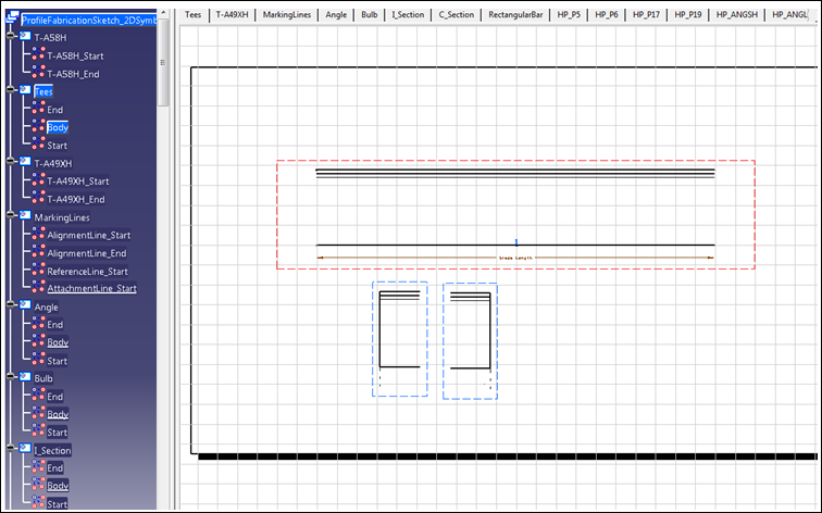
-
In order to see the definition points:
-
Select the geometry in the view using selection trap.
-
Right-click to open the context menu and click Properties.
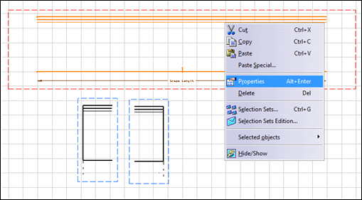
-
In the menu for Current selection you can see all the definition points for this detail.
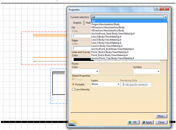
-
Select one, for example AnchorPoint_End, to make it the Current selection.
-
Modify its attributes as needed. Click OK.
Notes: Changing the position of a definition point will impact placement of other detailing symbols that are dependent on it.
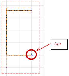
The image shows the anchor points defined in the body:
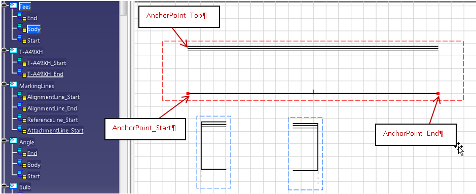
Start and End are defined on the axis, shown in blue. When the view is placed, the Start axis is matched with AnchorPoint_Start; the End axis is matched with the AnchorPoint_End.
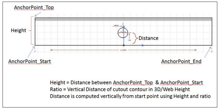
AnchorPoint_Top is defined in order to locate cutouts on stiffeners.
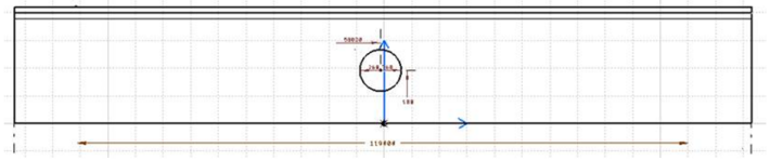
For Cutouts, two dimensions are placed onto the drawing to locate them: the horizontal distance from the start end of profile and the vertical distance from MoldedFlange1 (The face that will be in contact with Plate) The diagram below shows how cutout distance is computed using AnchorPoint_Top point.
-
VP_GO : Stands for Global Orientation point. This point will be used to locate the global orientation axis.
-
VP_UR: Stands for Upper Right point
-
VP_LL: Stands for Lower Left point
-
VP_LL and VP_UR points are used to define a rectangle inside which the view will be placed.
![]()