-
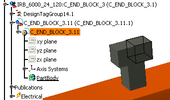
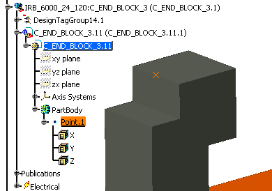
Expand the specification tree. To add a point to the block body, select and double click the part C_END_BLOCK_3.11 from our scenario.
The Electrical 3D Design Part workbench opens. -
Verify C_END_BLOCK_3.11 is highlighted (that is, the active part).
-
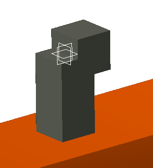
Select the C_END_BLOCK_2, and right-click Hide/Show.
-
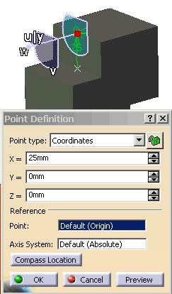
Select the compass and place it on the center of the edge of the block as shown.
-
From the Geometrical Element toolbar, click Point
 .
.
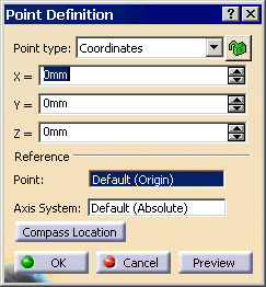
The Point Definition dialog box appears.
-
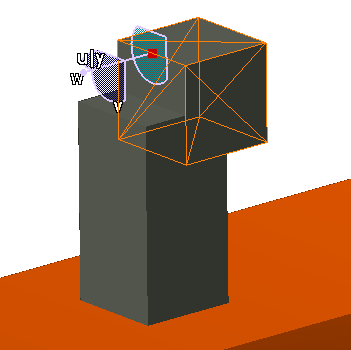
Click Compass Location bar; then click Preview to see the results in the 3D window. This gives you coordinates for the point.
-
To get the point in the center, adjust accordingly: X=25mm, Y=0, Z=0, then click OK.
The point appears in the 3D window and in the specification tree.
-
Select the C_END_BLOCK_2, right-click and select Hide/Show so it is shown.
-
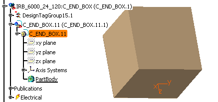
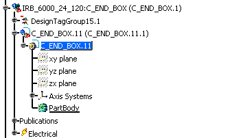
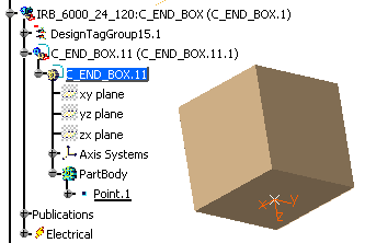
For the next connection point, expand the specification tree for the brown box, and double click on the C_END_BOX.11.
-
Verify C_END_BLOCK.11 is highlighted (that is, the active part).
-
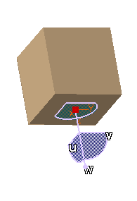
Select the compass and place it on the center of the bottom of the block as shown.
-
Click Point
.
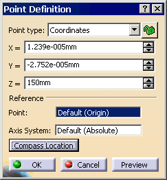
The Point Definition dialog box appears.
-
Click Compass Location bar; then click Preview to see the results in the 3D window.
-
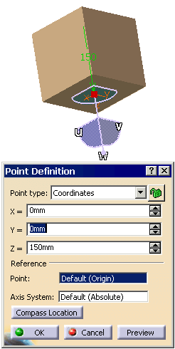
To get the point on the surface, adjust accordingly: X=0, Y=0, Z=150mm, then click OK.
-
Grab and move the compass. The point appears in the 3D window and in the specification tree.
-
Double click on the robot and cable at the top of the specification tree to bring you back into the Device Building workbench.
-
Change the name from Product1 to Robot and Cable. Right-click on the name, and select Properties. In the Product tab, change the Part Number.
-
From the menu, select, File > Save to save the two changes that you have completed.