- Accessing the Measure Item Dialog Box
- Defining Selection 1 and Selection 2 Modes
- Defining the Calculation Mode
Accessing the Measure item Dialog Box
To access the Measure Item dialog box:
-
Click Measure Item
 .
In DMU, you can also select Analyze > Measure Item from the
menu bar.
The Measure Item dialog box is displayed: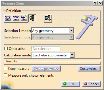

Notes:
-
When the Measure Selection is performed in the 3D Area, the original 3D element of the selected object is used for measure computation. By example, in the case of an Extract, it is the object on which the Extract has been performed, which is considered for the measure computation.
-
When the Measure Selection is performed in the Specification Tree, the selected object for measuring is exactly the one from the tree. In the case of an Extract, selecting in the Specification Tree enables to perform measure computation on the Extract object itself.
Dialog Box Options
-
Other Axis: when selected, lets you measure distances and angles with respect to a local V5 axis system.
-
Keep Measure: when selected, lets you keep the current and subsequent measures as features.

This is useful if you want to keep the measures as annotations for example.
Some measures kept as features are associative and can be used to valuate parameters or in formulas. For more information, see Updating Measures.
Note that in the Drafting and Advanced Meshing Tools workbenches, measures are done on-the-fly and are therefore not persistent nor associative and cannot be used as parameters.
-
Measure only shown elements check box: when selected, lets you measure only the elements from the show space.

- Swapping the elements between show and hide spaces does not modify the existing measurements.
- An update (automatic or manual) of the existing measurements is necessary to modify them after the swap.
- Select this check box before selecting any elements.
-
Create Geometry: Lets you create the points and line corresponding to the minimum distance result. For more information, see Creating Geometry from Measure Results.
-
Customize... : lets you customize display of measure results. For more information, see Customize Measure Between.
Accessing other measure commands
-
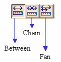
The Measure Between command is accessible from the Measure Item dialog box. Simply click one of the Measure Between icons in the Definition box to switch commands.
-
In DMU, the Measure Thickness command is also accessible from the Measure Item dialog box. For more information, see the appropriate task in the DMU Space Analysis User's Guide.
-
Defining the Selection 1 Mode
-
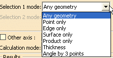
Any geometry (default mode): measures the properties of the selected item (point, edge, surface or entire product).
Note: As the geometric set is a collection of geometrical entities, the selection of Geometrical Set is not allowed. -
Point only: measures the properties of points. Dynamic highlighting is limited to points.
-
Edge only: measures the properties of edges. All types of edge are supported.
-
Surface only: measures the properties of surfaces.
In the last three modes, dynamic highlighting is limited to points, edges or surfaces depending on the mode selected, and is thus simplified compared to the Any geometry mode. -
Product only: measures the properties products.
Products can be specified by selecting product geometry, for example an edge or surface, in the geometry area or the specification tree.
-
Angle by 3 points: measures the angle between two lines themselves defined by three points.
-
To define lines:
-
Select three existing points in the geometry area or in the specification tree.
Note: You cannot select picking points. Smart selection is offered. This means that a sphere or circle, for example, are seen as points.
The resulting angle is always positive. It is
measured in a counterclockwise direction and depends on the order
in which points were selected as well as your viewpoint (the normal
to the plane is oriented towards you).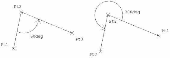
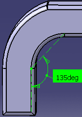
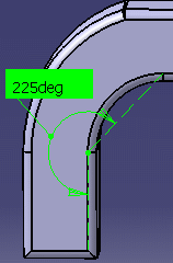
You can drag the angle line to show the complementary angle (360° - the initial angle measured).
You can also obtain the complementary angle when measuring the angle on arcs.
Note: The dialog box and knowledge parameters are refreshed. The value of the complementary angle is stored along with the measure.
-
Thickness (DMU only): measures the thickness of an item. For more information, see the appropriate task in the DMU Space Analysis User's Guide.
The Measure Item command:
-
lets you access the radius of an exact cylinder or sphere.
-
recognizes ellipse-type conic sections.

-
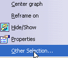
Using the Other Selection... command in the contextual menu, you can access the axis of a cylinder as well as the center of a sphere to, for example, measure between two cylinder axes.
Defining the Calculation Mode
-
Exact else approximate (default mode): measures access exact data and wherever possible true values are given. If exact values cannot be measured, approximate values are given (identified by a ~ sign).
-
Exact: measures access exact data and true values are given. Note that you can only select exact items in the geometry area or specification tree.
In certain cases, in particular if products are selected, a warning dialog box informs you that the exact measure could not be made. -
Approximate: measures are made on tessellated objects and approximate values are given (identified by a ~ sign). In design mode, the canonical type of surfaces (plane, cylinder, etc.) is not recognized.
Note: - Elements in No Show state are not taken into account during Update in the Approximate calculation mode.
- Measuring is not permitted on hidden elements in any of the calculation modes (Exact else approximate, Exact and Approximate).
- You can hide the ~ sign using the Tools > Options command (General > Parameters and Measure > Measure Tools).


