 |
-
Click the Break Surface or Curve icon:

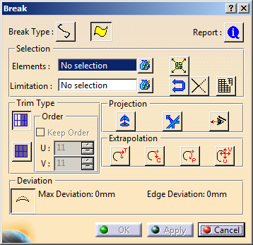
| The Break dialog box and the
Tools Palette appears. |
-
Click the Break Surfaces option:

| The Break dialog box content has been
modified according to the selected type. |
 |
|
The Break dialog box displays the following
information:
-
Break Type:
-
Selection
 |
- You cannot break a multi-cell body using a cutting
element at the cell boundary.
For example, it is not possible to break a multi-cell
curve by a point on one of its cell boundary.
- If the Break Type is changed,
the Elements field is cleared and
highlighted for new element selection.
-
You can directly select an
intersection curve resulting from a Cutting Plane
Analysis as limiting element while breaking
the surface.
- In case of selection by trap, only valid
elements (surfaces in case of Break Surface
and curves in case of Break Curves) are
selected.
|
 Limitation List: displays the list of
limiting elements. You can select the limiting elements or
instantly create an isoparametric curve as a limiting
element by clicking the surface to break, then position the
curve using the manipulator.
If you click anywhere near one of the edges
of the surface to break, the isoparametric curve is created
normal to the nearest edge.
By selecting the
Propagate
option from the contextual menu of the manipulator you can
propagate the isoparametric curve on to adjacent surfaces if
selected in the Break dialog box.
Clearing the Propagate
Isoparametric Curve contextual command before
creating an instant iso-parametric curve avoids propagation of
iso-parametric curve on to adjacent surfaces. For more information about the isoparametric curves, see
Creating
Associative Isoparametric Curves.
-
 Break Both: breaks elements to be cut and
limiting elements by each other.
-
Fragments:
fragments an input curve(s) or surface(s) without selecting the
Limitation inputs set. If you select a curve(s) or
surface(s) in the Elements input set and checks the
Fragment option, the Limitation input
selector would be inactive. Also, all the other options will be
inactive. Now when you press the Apply button the curve(s) or
surface(s) will be broken by its segment boundaries. Report
shows the status for the cutting elements. In this option as
there is no cutting element, report will always display “No
computation done”.
 |
- The curve can be a cutting element or an intersection
curve between surfaces of the cutting element and the
element to be cut.
- Extrapolation is done from both sides of curve.
- If there is no intersection between surfaces of the
cutting element and the element to be cut, the extrapolation
options even if available, do not have any effect.
- You can select
an edge
of a surface, as the
element to be cut.
|
-
 Report:
displays a status about cutting elements:
-
Cutting elements that can be used for the
Break (marked by a green tip). When you click on the text, the
corresponding curve is highlighted in green in the 3D geometry.
-
Cutting elements that cannot be used for the
Break (marked by the condition to be applied so that they can be used:
projection, etc). When you click on the text, the corresponding curve
is highlighted in red in the 3D geometry.
-
When there is no selection of cutting
elements, an error message is issued and the Break Report
panel informs you that no element is selected.
-
When a red cross is displayed, it means
that the problem cannot be managed by the application.
-
Max deviation: displays the
maximal deviation between original surface and the resultant surface in
the dialog box and on the geometry.
Available only with Break Curves and Trim Surface
options.
|
-
Select the surface.
-
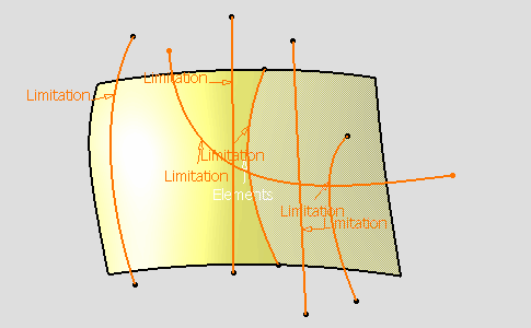
Select the Limitation field in the Break
dialog box and select the six curves as shown.
 |
- In case the limiting elements are unavailable,
you can click on the surface to create an
isoparametic curves on the surface. You can move the
isoparametric limiting curve using the manipulator
and also propagate the curve on to adjacent supports
(surface) selected in the break dialog box.
- Right-click on a Limitation tag to quickly
access contextual options for Extrapolation
and Projection which are also available
in the dialog box, as well as Propagate
Isoparametric Curve and Assemble.
|
-
Click Apply in the Break dialog
box.
| The surface has been trimmed. By default, only one trimmed
element is kept (no transparency has been applied) other not (a
transparency has been applied). |
 |
-
Click the curve segment to be kept: it
appears with no transparency in the 3D geometry.
-
Right-click any relimited element to display the
following contextual menu.
 |
- Keep all: all parts of the all
curves are kept.
- Keep all but this: all parts of all
curves are kept except the selected one.
- Remove all but this: all parts of
all curves are removed except the selected one.
|
| To keep, or do not keep, some elements press the Ctrl key and click them. |
-
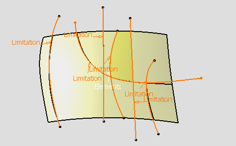
Click Along Compass
 . .
-
Click Apply in the Break dialog
box.
| Elements that do not lie on the trimmed elements
will be projected (pseudo-intersections) onto the trimming elements
according to the compass direction. |
 |
-
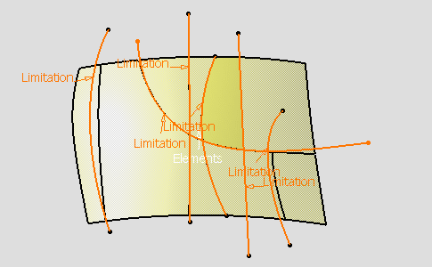
Click Along Normal
 . .
-
Click Apply in the Break dialog
box.
| Elements that do not lie on the trimmed elements
will be projected (pseudo-intersections) onto the trimming elements
according to the normal direction. The surface has been trimmed. |
 |
-
Click the Shorten Mesh option:

-
Click Apply in the Break dialog
box.
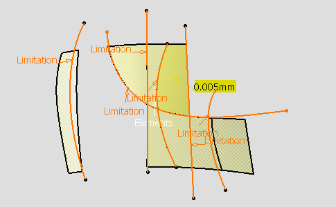
- The maximal deviation is displayed in the Break
dialog box and on the geometry (yellow label).
- The maximum degree variation allowed for each
patch of the new surface as compared to patches of the initial surface can
be modified.
- Click the U Order and the V Order text
to edit and modify the values (besides is an example with U and V values
set to 8).
|
 |
-
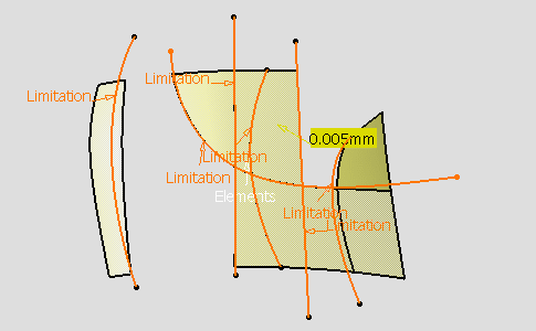
Click the Tangential Extrapolation option:
 . .
-
Click Apply in the Break dialog
box.
| As a consequence, one edge is added. |
 |
-
Optional: Click the IsoUV Extrapolation
option.
-
Click Apply.
The input elements are trimmed by extrapolating the limiting
elements. By default, the shortest Iso side in U direction is
taken to trim the surface.
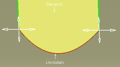
4-directional arrow manipulators are provided at the end points
of the limiting elements for selecting any of the Iso-extrapolated
sides to trim the surface in both IsoU and/or IsoV direction. |
-
Click one or more arrows to select the required Iso
side(s).
You see the trim result in the direction of the clicked
arrow manipulators.
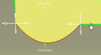
 |
- Undo/Redo is provided for arrow manipulator
selection.
- Arrow manipulators are provided only if
extrapolation is required in case of IsoUV
Extrapolation option.
|
|
-
Click OK in the Break dialog box.
 |
Keep Original option setting in the Tools
Dashboard is locally saved for the Break command when the
command is exited by clicking OK. When you re-launch
the Break command, the previous session's Keep Original
option setting is available. |
|
![]()