 |
This task shows you how to temporarily display
furtive elements such as control points, segmentation, iso-curves and the
free edges of the geometry being created while in a FreeStyle command.
Once you exit this command, these elements are removed as opposed to
those displayed using the permanent visualization options (see
Setting FreeStyle Visualization Options). |
 |
-
Open the
FreeStyle_Part_44.CATPart document.
-
Select the options in the Tools > Options > Shape > FreeStyle
> Manipulators > Furtive Display Variants section.
For more information about Furtive Display Variants settings,
see CATIA Infrastructure User's Guide: Customizing: Shape,
Manipulators,
Furtive Display Variants.
|
 |
-
Click the Match Curve
 . .
-
Click the Furtive Display
 . .
-
Successively select two curves. The first curve is
automatically modified so as to be connected to the second curve.
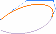
| Control points are displayed in
blue on the matched curve. |
-
Click OK in the current command.
 |
 |
- Multi-selection is available,
meaning that if several elements are involved in the current command, if
there were two curves to be projected for example when using the Project Curve icon
 the control points are displayed on all the resulting elements.
|
|
-
Click Styling Extrapolate
 . .
-
-
-
-
|