 |
-
Click the Break Surface or Curve icon:

| The Break dialog box and the Tools Palette
appear. |
-
Select the Break Curves option if needed:

| The Break dialog box content has been modified according
to the selected type. |
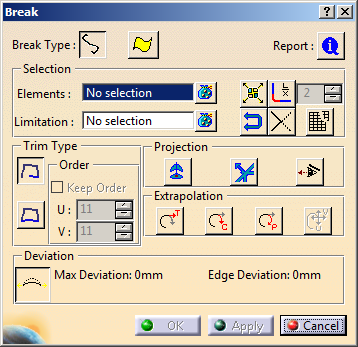 |
The Break dialog box displays the following information:
-
Break Type:
-
Selection
-
Elements: defines the set of curves or surfaces
to be cut.
-
Limitation: defines the set of limiting elements
such as
points, curves, planes or surfaces.
 |
- You cannot break a multi-cell body using a cutting
element at the cell boundary.
For example, it is not possible to break a multi-cell
curve by a point on one of its cell boundary.
-
You can directly select an
intersection curve resulting from a Cutting Plane
Analysis as limiting element while breaking
the surface.
- If the
Break Type is changed, the Elements
and Limitation
fields are cleared and the Elements field
is highlighted for new element
selection.
|
-
 Invert Selection:
You can use this option to invert (move) the selection from the
current state to the other state depending on the allowed
selection type of the other state. For example, if, by mistake,
you select three surfaces and one curve in
Limitation
state with Break
Surface as the break type, and then just press the
Invert Selection option to move all the three surfaces to the
Elements
state provided, the current state is
Limitation.
With this option, all the elements in the current state are
moved to the other state. Note that the curve will not be moved
to the Elements
state, as selection of
1D elements
is not allowed in the
Elements
state with the break type
Break Surface.
So the curve will remain in the
Limitation
state.
-
 Disassemble:
You can use this option to disassemble multi cell/domain bodies
into mono cell bodies. When this option is unchecked, and you
select a multi cell/domain body as Elements input and break it
using a curve such that only one cell/domain is broken by this
curve, the result should contain only two elements. But when
this option is checked, the multi cell/domain results are
disassembled into mono cell bodies.
- Fragments:
Fragments an input curve(s) or surface(s) without selecting the
Limitation inputs set. If you select a curve(s) or
surface(s) in the Elements input set and checks the
Fragment option, the Limitation input
selector would be inactive. Also, all the other options will be
inactive. Now when you press the Apply button the curve(s) or
surface(s) will be broken by its segment boundaries. Report
shows the status for the cutting elements. In this option as
there is no cutting element, report will always display “No
computation done”.
- Break in to
equal number:
Only available in case of Break Curves break type. You can use
this option to break an input curve/s into ‘x’ equal parts
without selecting the Limitation inputs set. If you
select a curve in the Elements input set and checks
this option, the Limitation input selector will be
inactive. Also, all the other options except relimitation
options will be inactive. You have to specify the number parts
you want to break each curve into, through the spinner provided.
When you press the Apply button each curve will be
broken into ‘x’ equal parts. Report shows the status for the
cutting elements. In this option as there is no cutting element,
report will always display “No computation done”.
- Keep order
with surface trim: In case of
surface trim option, the maximum deviation, if any, between the
original and the resulting outputs are shown in the dialog box
as well as in the 3D. The command is migrated to the new common
architecture for the Freestyle and Automotive Class A.
- Trap
Selection:
If you drag a trap in the
model, all included elements will become selected. If no
modifier was pressed, the current selection is emptied and only
the included elements in the trap become selected. If CTRL is
pressed while creating the trap, the included elements are added
to the current selection.
In case of
selection by trap, only valid elements (surfaces in case of
Break Surface and curves in case of Break Curves)
are selected in the Elements and Limitation fields.
- Stack
command under Limitation:
- When the
Curves option is selected, the Limitation input
editor is stacked with the following commands:
- Create Point:
On selection of input curve element, you can create an
limiting point element directly by clicking on the curve or by
using the Create Point contextual menu command. When
you move the pointer over the curve, the pointer displays a red dot
that helps you create the point. Using this you do not need to go via the contextual
menu command of the
Limitation field.
Create Midpoint
- Create Plane
- Create Join
- When Surfaces
option is selected, the
Limitation
input is stacked with the following commands:
- Create Plane
- Create Isoparameter:
On selection of input surface element, you can create an
limiting Isoparameter element directly by clicking on the
surface or by using the Create Point contextual menu command.
When you move the pointer over the curve, the pointer displays a red dot
that helps you create the point. You do not need to go via the
contextual menu command of the Limitation field.
- Create 3D Curve
- Create Join
 |
- If there is an intersection between the cutting
element and the element to be cut, the extrapolation
options even if available, do not have any effect.
- Using the Break Both
 option:
- You can extrapolate the element to be cut.
- The vertex of cutting element closest to the
element to be cut, is used to extrapolate the
cutting element, and vice versa.
- If proper result is not obtained with this vertex,
the vertex at other end of the respective element is
used for extrapolation purpose.
- In case of multi-domain cutting element, domain that
has closest vertex to the element to be cut is used for
extrapolation.
|
-
Report: displays a status about cutting elements:
-
Cutting elements that can be used for the Break (marked by a
green tip). When you click on the text, the corresponding curve
is highlighted in green in the 3D geometry.
-
Cutting elements that cannot be used for the Break (marked by
the condition to be applied so that they can be used: projection,
etc). When you click on the text, the corresponding curve is highlighted
in red in the 3D geometry.
-
When there is no selection of cutting elements, an error message
is issued and the Break Report panel informs you that
no element is selected.
-
When a red cross is displayed, it means that the problem cannot
be managed by the application.
-
Max deviation: displays the maximal deviation
between original surface and the resultant surface in the dialog box
and on the geometry. This is available only with Break Curves and
Trim Surface
options.
|
-
Select the curve.
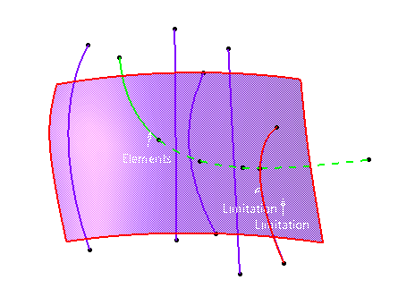
| The element to be cut appears in the green color. |
-
Select the Cutting field in the Break
dialog box and select the surface and the curve as shown.
| The cutting elements appear in the red color. |
-
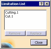
Click the Limitation List icon:

| The Limitation List dialog box appears. You can manage inside
this dialog box the limiting elements: remove or replace. |
 |
-
Click Close in the Limitation List dialog box.
 |
Right-click on a Limitation tag to quickly access
contextual options for Extrapolation and
Projection which are also available in the dialog box. |
-
Click Apply in the Break dialog box.
Only the green elements are trimmed. By default, only one
trimmed element is kept (plain line) other not (dashed line).
After breaking the cut element (in green color) the part of element
which is kept is shown by plain line and other not kept will be
shown in dashed line. |
 |
-
Click the curve segment to be kept: it
appears with a plain line in the 3D geometry.
-
Right-click any relimited element to display the following
contextual menu.
 |
- Keep all: all parts of the all curves are kept.
- Keep all but this: all parts of all curves are kept
except the selected one.
- Remove all but this: all parts of all curves are removed
except the selected one.
|
|
To keep, or do not keep, some elements press the Ctrl key and click them. |
-
Click the Along Compass option:

-
Click Apply in the Break dialog box.
| Elements that do not lie on the trimmed elements will be projected
(pseudo-intersections) onto the trimming elements according to the compass
direction. |
 |
-
Optional: In the Extrapolation
area, select an extrapolation type.
If element and limitation curves are not intersecting each
other, they can be extrapolated. Use the options available in
the Extrapolation area to specify the type of extrapolation. The
intersection points are used to break the input curves.
Each selected curve is provided with a point manipulator at its
center to choose vertices of the curves for extrapolation.
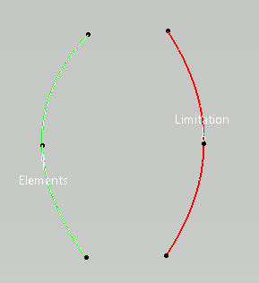
Each manipulator has 4 states:
- Closest: Default. The closest
vertices are extrapolated.
- Start: A single-directional arrow
manipulator pointing to the curve's start vertex is
shown in addition to the point manipulator. The
start vertex is extrapolated.
- End: A single-directional arrow
manipulator pointing to the curve's end vertex is
shown in addition to the point manipulator. The end
vertex is extrapolated.
- Both: A bi-directional arrow
manipulator pointing to both curve's start and end
vertices is shown in addition to the point
manipulator. Both vertices are extrapolated.
|
The Start manipulator is reached by clicking on the
point manipulator. A click on the start manipulator will change
its direction to End and vice versa. Closest and Both
manipulator states are reached through the contextual menu on
the point manipulator.
 |
In case of multi-domain curve bodies, no
manipulators are provided on the curves when selected.
The closest domain of that body is considered for the
extrapolation. |
|
-
Click on the element's point manipulator.
An arrow manipulator is shown pointing in the direction of
the curve's start vertex.
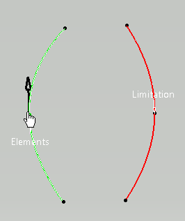 |
-
Click Apply.
The curve is extrapolated at its start vertex.
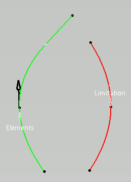 |
-
Click OK in the Break dialog box.
|
![]()