There are two commands for an analysis using cutting planes:
|
The command functionalities of both analyses are identical.
Open the CuttingPlane1.CATPart document.
-
Select the surfaces to be analyzed.
-
Click Cutting Plane Analysis
 in the Shape Analysis toolbar.
A reference plane is displayed along with the default number of cutting planes, and the corresponding projected lines onto the selected surface. 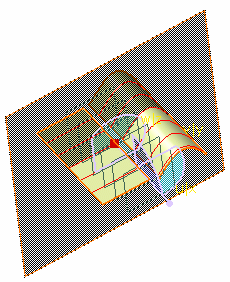
The Cutting Plane Analysis dialog box appears. 
If you click Global cutting Plane Analysis in the Generic Tools toolbar, the Global Cutting Plane Analysis dialog box appears. You can clear or select Activate/Deactivate global cutting plane analysis and Activate or deactivate Auto-Apply options in the Global Options area if required. 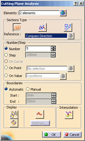
You can define analysis parameters from this dialog box:
- Activate/Deactivate global cutting plane analysis: If this button is selected (default), the analysis is created and displayed in the work area. If it is cleared, global analysis is deleted, and no global analysis will be created afterwards, even if you add, modify, or delete elements.
-
Activate or deactivate Auto-Apply
 : If
this button is selected (default), the analysis updates itself
immediately on changing any option. If it is cleared, you can select all
inputs and then press Apply button to compute the analysis.
: If
this button is selected (default), the analysis updates itself
immediately on changing any option. If it is cleared, you can select all
inputs and then press Apply button to compute the analysis.
-
Elements: You
can add surfaces to be analyzed. This option is only available in
Cutting Plane Analysis dialog box.
The icon
lets you edit the list of surfaces selected for analysis. Click the icon to
display the Input Elements List dialog box that allows you to
remove or replace an surface.
icon
lets you edit the list of surfaces selected for analysis. Click the icon to
display the Input Elements List dialog box that allows you to
remove or replace an surface.- The Geometric Set or valid elements (surfaces) under it can be selected as input elements. The entire geometric set is not added as input on selection; only the surfaces under it are added. Press Ctrl key for multiple selection of geometric sets.
- Scan or tessellation surfaces can be selected as input elements.
-
The plane in which the analysis is to be
performed, using the three icons (Parallel planes
 ,
Planes
perpendicular to curves
,
Planes
perpendicular to curves
 ,
Independent planes
,
Independent planes
 ).
). -
You can select the reference element in the Sections Type
area. The field changes depending
on the type of analysis:
- In case of Parallel planes option, the field name is Reference and allows you to select the direction of reference plane. You can select the default planes (xy, yz, zx planes) or compass direction as reference element. These selection options are available in the contextual menu or can be selected from geometry or specification tree. The default direction is given by compass.
-
In case of Planes
perpendicular to curves option, the field name is Curves,
allows you to select a curve or a surface edge as reference element. If On
curve option is selected, multiple selection of curves is not
possible and thus the
option
is not selectable.
In this case, if Geometric Set is selected, all the curves under it are added in the reference field. - In case of
Independent planes option, the field name is Planes,
and allows you to select the reference plane. You can select default planes
(xy, yz, zx planes) or create a plane. These selection options are
available in the contextual menu or can be selected from geometry or
specification tree.
In this case, if Geometric Set is selected, all the planes under it are added in the reference field.
-
Number/Step
- Number, Step: Choose whether you have a set number of planes or a distance (step) between two planes. In the latter case, the number of planes depends on the size of the analyzed area. This option is only available in Parallel panes and Planes perpendicular to curves mode.
- On curve: Allows you to create perpendicular planes. This option is only available in Planes perpendicular to curves mode. If this option is selected, only one curve could be selected at a time.
- On Point: Allows
you to a create plane passing through a point. You can select an
existing point or create a new point. To create a new point, right-click
in the point field and select Create Point.
This option is available in:- Parallel planes: The plane is created passing through the selected point and parallel to the reference plane defined by the compass. This reference point from which the plane position is defined is the origin of global axis system.
- Planes perpendicular to curves: The plane is created passing through the selected point and perpendicular to the curve. This reference point from which the plane position is defined is the extremity of the curve which is closest to the origin of global axis system.
- On Value: Allows
you to a create plane at the specified value from the global axis
system. To enter values click
. The
Value List dialog box appears that allows you to enter new
values and further edit them. Multiple planes can be created by entering
required values. Every new value creates a new plane.
This option is available in:- Parallel planes:
The plane is created at the specified value with respect to the reference point.
You can also create a plane passing through a pointed position on the geometry. Select a point (on the fly) on the geometry. The pointed position is projected on the axis defined by the compass and the computed value is shown in the value field.
In both the cases, the cutting plane is created parallel to the reference plane defined by the compass. The reference point from which the plane position is defined is the origin of global axis system. - Planes
perpendicular to curves:
The plane is created at the specified value with respect to the reference point.
You can also create a plane passing through a pointed position on the geometry. Select a point (on the fly) on the geometry. The pointed position is projected on the curve and the computed value is shown in the value field.
In both the cases, the cutting plane is created perpendicular to the curve. The reference point from which the plane position will be defined is the extremity of the curve which is closest to the origin of global axis system.
- Parallel planes:
-
The boundaries of the set of planes (available
in Parallel planes mode only):
- Automatic: The analysis is performed based on all selected surfaces bounding boxes. The cutting planes are evenly distributed within this area, one being necessarily located on the reference plane if the Step option is active.
- Manual: The analyzed area is defined by the Start and End values.
- Start/End: The Manual mode defines the distance at which the first (start) and last (end) cutting planes are located on the reference plane axis.
-
Display options facilitating the analysis reading:
-
 Planes:
Activates/hides the representation of the
cutting planes.
Planes:
Activates/hides the representation of the
cutting planes. -
 Arc Length: Displays the length of each section cut
created.
Arc Length: Displays the length of each section cut
created. -
 Curvature:
Activates the display of the curvature comb.
Curvature:
Activates the display of the curvature comb. -
 Interpolation: When
activated it computes interpolated NURBS curves when
cloud/mesh surfaces are sectioned. If deactivated, polyline section
curves are computed.
Interpolation: When
activated it computes interpolated NURBS curves when
cloud/mesh surfaces are sectioned. If deactivated, polyline section
curves are computed.
- In case of datum surfaces, cutting plane analysis computes the intersection curves independent of the Interpolation option selected.
- The selection of Curvature Analysis and Interpolation option buttons are independent to each other.
- The curvature snalysis can be performed on the interpolated NURBS curves and intersection curves, however not on polyline section curves.
-
If you click the Settings button, the Porcupine Curvature dialog box appears. 
Clicking the Display diagram window  opens the 2D Diagram. This curvature analysis command is only available with the Freestyle Optimizer
license.
opens the 2D Diagram. This curvature analysis command is only available with the Freestyle Optimizer
license.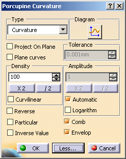
See Performing a Curvature Analysis. -
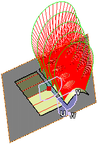
Click Parallel planes
.The compass moves to the reference plane center, and then you can manipulate the reference plane. 
If you want to perform an analysis in planes perpendicular to curves, select a curve and click the Planes perpendicular to curves .")
Using the Planes perpendicular to curves type, you can select the On curve option in the Number/Step area to create perpendicular planes: - Select a reference curve.
- Select the On curve option.
")

You can create several planes: right-click the reference plane and select Keep this plane from the contextual menu.
Planes are added to the specification tree.
The Keep this point option is also available from the contextual menu. For more information see FreeStyle Shaper, Optimizer & Profiler: Generic Tools: Editing and Keeping a Point.This option is only available with the Planes perpendicular to curves type. If you want to perform an analysis in independent planes, click Independent planes .")
You can use the contextual menu in Planes field to create the a plane.
Each created plane is added to the current list of planes used for the analysis. See Stacking Commands for further information. -
Select the Manual mode, set the Step value to 30, and the Start value to -150 and End value to 150.
The planes are automatically relocated. 
-
Click Arc Length
. The arc lengths are
displayed.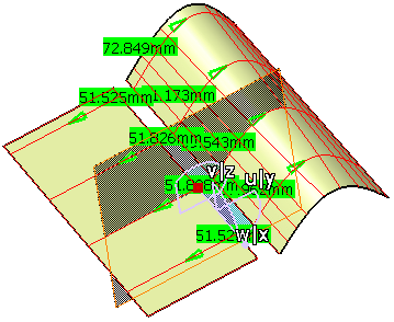
-
Click OK in the Cutting Plane Analysis dialog box, when you have finished the analysis.