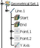
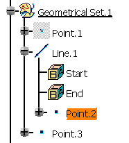
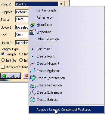
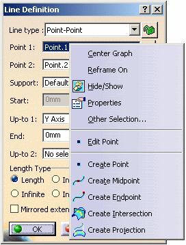
This task shows how to stack commands, that is create another basic object in the current command without leaving it.
Open a new CATPart document.
-
Click Line
 .
.The Line Definition dialog box appears. -
Use the combo to choose the desired line type.
Here we chose the Point-Point line type: two points are required to create the line. 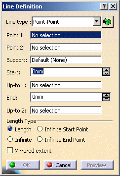
As no point already exists, you will have to create them. -
Right-click the Point 1 field.
-
Select Create Point.
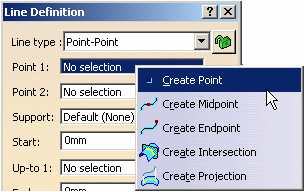
The Point Definition dialog box appears, as well as the Running Commands window that shows you the history of commands you have run. This informative window is particularly useful when many commands have already been used and stacked, in complex scenarios for instance. 
-
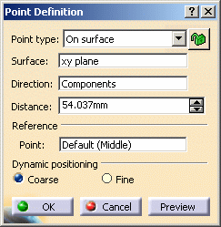
Use the combo to choose the desired point type and select the On surface type.
-
Choose the xy plane as the Surface.
-
Right-click the Direction field and select the X Component contextual item.
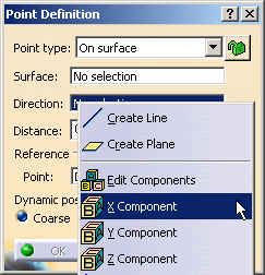
- You can select the Edit Components contextual item to edit the components' directions (X, Y or Z).

- When the command is launched at
creation, the initial value in the Axis
System field is the current local axis system. If no
local axis system is current, the field is set to Default.
Whenever you select a local axis system, the direction's coordinates are changed with respect to the selected axis system so that the direction is not changed. This is not the case with coordinates valuated by formulas: if you select an axis system, the defined formula remains unchanged.
This option replaces the Coordinates in absolute axis-system option.
-
Select 50mm as the Distance.
-
Click OK.
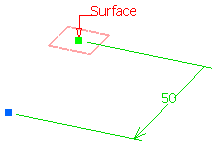
The Point Definition dialog box closes and you return to the Line Definition dialog box. The Point.1 field is valuated with the point you have just created. -
Right-click the Point 2 field.
-
Repeat steps 5 to 9 (select 150mm as the Distance).
The Point Definition dialog box closes and you return to the Line Definition dialog box. The Point.2 field is valuated with the point you have just created and a line is previewed between Point 1 and Point 2. 

-
Right-click the Up-to 1 field and select the Y Axis contextual item.
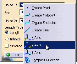
An infinite datum line corresponding to the Y Axis of the compass direction will be created. 
-
Click OK to create the line.
- In case of a multi-list (like in the Spline or Fill commands), the contextual menu changes depending on the selected column, the feature type (point, line, etc.) and the mode (creation or edition).
- You can edit the created line and access generic contextual commands such as Center Graph, Reframe On, Hide/Show, Properties, and Other Selection.
For Center Graph and Reframe On, refer to the Part Design User's Guide. For Hide/Show, refer to Hiding Objects, for Properties, refer to Displaying and Editing Graphic Properties, and for Other Selection, refer to Selecting Using the Other Selection... Command. All these chapters can be found in the CATIA Infrastructure User's Guide. These commands can also be accessed contextually from the specification tree. - In case of stacked commands that do not have a dialog box (Create MidPoint, Create EndPoint, Create Extract (in point), Create Extract (in tangency), etc.), if you want to return to the stacking command, you need to select Undo from the Edit menu bar.
- Stacked commands are created using the Keep mode, therefore they do not absorb their inputs.
- The children that appear under any feature may not follow the same order as their order of creation.
![]()
