- Handle annotation leaders, by performing such operations as adding or removing a breakpoint, an extremity or an interruption.
- Move and position leader breakpoints.
Multi-selection restrictions:
- For all operations described in the Handling Leaders section below (except for changing the symbol shape - see next comment), multi-selection is not taken into account. The operation will be performed only on the leader you right-click in the selection.
- Changing the symbol shape behaves differently depending on whether
one or several annotations in the selection have more than one leader:
- If the leader you right-click is the only one in the annotation, then the symbol is applied to this leader and to all annotations which have only one leader.
- If the leader you right-click is not the only one in the annotation, then the symbol is applied to this leader only.
About associative and non-associative annotations:
When you create an annotation, a type of leader is automatically set, provided the standard files have not been modified. If you choose the Automatic option, a default symbol will be used, depending on the standard type, on the annotation type, and on whether the leader is associated to an element or not:
- If the leader is associated to an element:
- Unfilled arrow for ANSI / ASME
- Open arrow for ISO / JIS
- If the leader is not associated to an element:
- Unfilled circle for ANSI / ASME
- Filled circle for ISO / JIS
Handling Leaders
-
Right-click the yellow manipulator at the end of the leader.
The leader's contextual menu is displayed.
-
Choose from the available options.
-
To add a breakpoint, select Add a Breakpoint. Then, to remove this breakpoint, right-click the breakpoint and select Remove a Breakpoint.
-
To add an extremity to an existing breakpoint, right-click the breakpoint, select Add an extremity, and then click in the sheet to position the extremity. See, Arrow or leader orientation.
")
Notes: - You can add an extremity only in the case of a text or a welding symbol.
- If the leader extremity is perpendicular to a reference, an orientation link is created between the leader and the reference.
Then, to remove this extremity, right-click the yellow manipulator on the additional extremity and select Remove Leader/Extremity.
")
Right-clicking the yellow manipulator on the main leader extremity will remove the leader. 
-
To add an interruption, select Add an Interruption and then, on the leader, click the two points between which you want to add the interruption. Then, to remove this interruption, right-click the leader yellow manipulator and select Remove Interruptions.
Any existing interruption will be removed from the leader when adding or removing breakpoints. 
-
To remove the leader, select Remove Leader/Extremity.

-
To add an extremity link, select Add Extremity Link and then, select any reference element. You can replace, remove, or make this link perpendicular.
-
To add an application zone symbol, point to Application Zone. Then select No Zone if you do not want a symbol, or select the required symbol from the following available symbols:
For example, to add an all around symbol, select Global All Around.
These symbols are used to specify that a specification is to be applied all around, all about or all over the 3D profile of a part. You can also specify whether it is to be applied globally or partially. This complies with ISO, JIS and ASME international standards.
-
To modify the leader symbol shape, point to Symbol Shape. Then, select No Symbol if you do not want a symbol for the leader, or select the symbol you want from the available symbols.
You can remove the leader extremity symbol for all annotations.
-
-
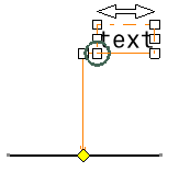
You can also move the leader or any existing breakpoints by dragging the yellow control point.
-
To move the annotation but not the leader, click the annotation and move it using the mouse.
-
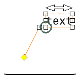
To move the leader along with the annotation while making sure the leader keeps its original shape, select Rigid and then move the annotation.
- This functionality is available for texts, welding symbols, 2D components, tables and geometrical tolerances, but not for other annotation types.
- This functionality also applies when rotating the annotation
text using the Free Rotation
 command.
-