- The cache can remember the geometry options selected. So next time you launch the symmetry command, the Symmetry options are selected by default.
- In Tools > Options > Infrastructure > Part Infrastructure > General, if the option Restrict external selection with link to published elements is selected and locked by administrator, symmetry is created only for published elements. The symmetry creation is not affected by the publish status of the elements, if this option is selected and unlocked.
- The Part Body (or Main Body)
- The External View
- All Axis Systems
- All Bodies other than the Part Body.
- All Geometrical Sets, ordered or not
- Any combinations of the previous elements using the
Customize option.
In symmetry part, the Body, PartBody, GS or OGS would contain only result of the geometries corresponding to the tool in original part, with or without link (depending upon your preference). The number of features in the result will be the same as we get it using paste special as result.
- The Keep link in position and Keep link with geometry options are grayed out in the Assembly Wizard dialog box, while a Part Design license (PD1 or GSD) is not granted.
- Assembly features do not appear in the specification tree, while the Assembly Design license (ASD) is not granted.
-
Click Symmetry
 in the Assembly Features
toolbar.
in the Assembly Features
toolbar.The Assembly Symmetry Wizard dialog box displays, prompting you to select the reference plane. 
-
Select the element used as the reference of the symmetry.
This element can be a plane or any planar face that the system recognizes as a plane. 
Components Chosen for Duplication
The component you select for duplication must be the child of the active product.
Example 1: the element to duplicate is not a symmetrical element
In this case, the symmetrical element is a new component.
-
Select the product to be duplicated.
The selected product is highlighted and the symmetry is previewed. 
- The Assembly Symmetry Wizard
dialog box appears:
It displays the list of all elements that are duplicated, that is all components composing of the selected elements. - The three icons to the left of the window represent symmetries as well as the creation of new components.
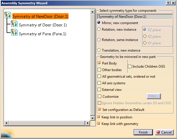
The Rotation, same instance option moves the selected geometry symmetrically in relation to a plane.
It does not create any new geometry.
In short, the Bill of Material is not affected by the resulting geometry.
For an example, please refer to Rotating a Component by Using the Symmetry Command.
- If you want to preview the symmetry of a product, select Symmetry of part (part.x).
-
Instead of new components, you can also create
new instances of existing symmetries.
To do so, select them and check the option Rotation (new instance). For more about this option, refer to Example 2.
- The Assembly Symmetry Wizard
dialog box appears:
-
Click Finish to confirm the operation.
The Assembly Symmetry Result dialog box appears. Three new components have been created. 
-
Click Close.
You obtain a new component. 
- The new component is displayed as well as the parts it contains.
-
A new entity Assembly features also
appears in the specification tree.
It contains the symmetry referred to as Assembly Symmetry.1 which in turn contains the symmetry plane and the affected component.
Editing of the assembly symmetry components is not available with the P1 license.
More About the Mirror, new component Option
Once you have created a symmetrical component using the Mirror, New component option, you cannot apply the Symmetry command with the Mirror, New component option to any instance of the initial component (even if the reference plane is distinct).
Example 2: the element to duplicate is a symmetrical element itself
In this case, the symmetrical element is the new instance.
-
Click Symmetry
. -
Select the element used as the reference of the symmetry.
-
Select a component.
The component is highlighted and the symmetry is previewed. 
The Assembly Symmetry Wizard dialog box appears. It displays the list of all elements that are duplicated: all components composing product. -
Select Symmetry of Part (part.x) from the list. Only the symmetry of that component is now previewed in the geometry area.

-
Check the Rotation, new instance option.
A new icon reflects this change in the list. 
-
The object is positioned with respect to selected reference.
Now, as it is intrinsically symmetrical, you need to define which of its three reference planes must be symmetrical with respect to the reference.
For example, check XY plane option.It is moved accordingly. 
-
Check YZ plane option.
It is re-positioned. 
-
Click Finish to confirm the operation.
The Assembly Symmetry Result dialog box appears. Two new components and one instance have been created. 
-
Click Close.
-
The new component is displayed in the specification tree.
It contains one new instance and one new component. - The Assembly features entity contains the new symmetry referred to as Assembly Symmetry.2 which in turn contains the symmetry plane and the affected component.
-
The new component is displayed in the specification tree.
Translation
-
Click Symmetry
. -
Select the element used as the reference of the symmetry.
-
Select the required component.
The component is highlighted and the symmetry is previewed. 
-
Check the Translation, new instance option.
A new icon reflects this change. 
To calculate the translation, the application projects the center of the axis system onto the plane you selected.
The distance between the center and the plane is repeated twice.
-
Click Finish to confirm the operation.
The Assembly Symmetry Result dialog box appears. One instance has been created. 
- The new instance is displayed in the specification tree.
- The Assembly features entity contains the new symmetry referred to as Assembly Symmetry.3 which in turn contains the symmetry plane and the affected component.
-
Click Close. The wheel is translated:
About Geometry to be Mirrored in New Part
Keep Link Options
- The Keep link in position option guarantees associativity with the initial part or product: if you edit their positions, symmetrical elements inherit these modifications and are therefore repositioned accordingly.
- The Keep link with geometry option
guarantees associativity with the geometry of the initial part: if you
edit its shape, symmetrical elements inherit these modifications. However
this type of associativity is restricted to elements made visible via the
External View... command or to Part Bodies. For more information, refer
to Generative Shape Design User's Guide and Part
Design User's Guide respectively.
You can also use the Remove All Geometry Links contextual command on the symmetry object in the specification tree: right-click the symmetry_name object then select Remove All Geometry Links. The result is the same as if you unselect the Keep link with geometry option.
New Components or New Instances?
If you compare the symmetry obtained by using
the Mirror, new component option to the symmetry obtained first
using the Mirror, new component option, then the Rotation,
new instance option, then reselect Mirror, new component,
both results are different as indicated by the icons:
The behavior is the following: after changing
the symmetry type, that is Rotation, new instance, to reuse the
Mirror, new component option, the children of the product to be
mirrored remain as new instances whereas the product is assigned the
new component definition.
What you need to do
To make sure that you obtain the same results
for both operations, you need to use the Mirror, new component, all
children contextual command available in the dialog box instead of
checking Mirror, new component.
Result:
For more information about the Symmetry
command, refer to Modifying a Symmetry.
- CATIA does not automatically loads the required data from product which has symmetry, even if the option Compute exact update status at open is set to Automatic in Tools > Options > Mechanical Design > Assembly Design > General tab.
- If the option Keep link in position is selected for creation of symmetric part, then it is not advised to move it in 3d space using Fix in space.
Assembly Symmetry Behavior for Broken Link
The Mirror, new component option is available only when all the parts are loaded in the design mode. If there is any broken link (part is not loaded), a warning message is displayed, stating which part needs to be loaded. The Rotation and Translation options are available in case of broken link.
About change in the name of a body after performing a symmetry during assembly design