Occlusion culling

Occlusion culling enabled
If this option is selected, it means that occlusion culling is activated.
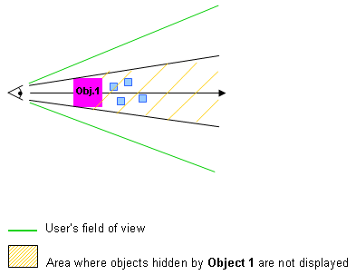
Occlusion culling avoids redisplay of hidden elements, particularly useful when viewing highly compartmented scenes such as plants and buildings and improves display performance.
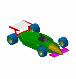
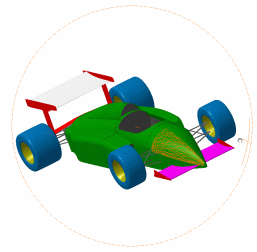
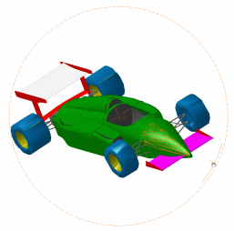
Let's have a look at the picture below to see what happens when occlusion culling is activated:
3D Accuracy
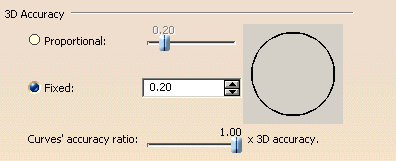
You have two choices (the preview area to the right shows you the effect of each setting):
Fixed
Sets a fixed sag value (from 0.01 to 10) for calculating tessellation on all objects, which does not vary with object size.
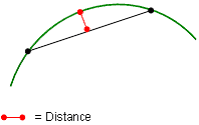
The sag value defines the chordal deviation for curves and surfaces.
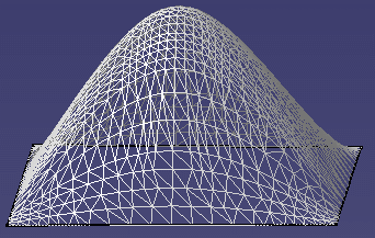
The "curve chordal deviation" represents the maximum distance between a polyline ("chord") whose end points lie on a curve and a point on this curve:
- A low value means that a very fine mesh is used to render surfaces
because the distance between the geometry and the triangles in the
tessellation is very low.
However, the drawback is that geometry is redrawn more slowly when using the viewing tools.
Example with default fixed sag value (= 0.20)
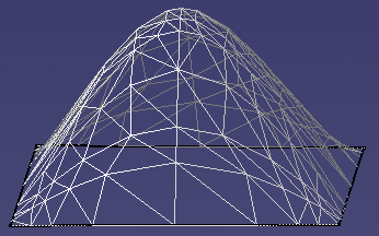
- A high value increases the distance between the geometry and the triangles and thus, decreases the number of triangles computed on the object. This means that a very coarse mesh is used, but the advantage is that geometry is redrawn more quickly.
Example with default fixed sag value set to 8.5
Proportional to element size
Tessellation is calculated according to object size: the larger the object, the coarser the tessellation. For the same sag value, the tessellation on small objects is always finer than on large objects.
The sag value used to calculate the tessellation of each object is calculated is as follows:
sag = coeff. x radius of sphere/100
where:
- "coeff." is the value you set using the slider (between 0.1 and 1)
- "radius of sphere" is the radius of a sphere encompassing the object entirely (this value is obviously higher on larger objects).
More precisely, let's take an example with the following bounding sphere with a radius 100:
 |
Sphere with radius 100 encompassed by its bounding sphere (in red):
 |
You can see that: radius of the bounding sphere > radius of sphere.
The formula used to compute the proportional sag refers to the radius of the bounding sphere (which is > 100), hence a coarser sag.
Mathematically speaking:
-
Fixed
Fixed_sag = 0.2 (expression 1) -
Proportional
Prop_sag = coeff x radius_of_bounding_sphere / 100 -
If coeff = 0.2 then
Prop_sag = 0.2 x radius_of_bounding_sphere / 100 (expression 2) -
As the bounding sphere of a sphere encompasses
that sphere (see pictures above) then
radius_of_bounding_sphere > radius_of_sphere -
If radius_of_sphere = 100 then
radius_of_bounding_sphere > 100 -
By dividing left and right members by 100 then
radius_of_bounding_sphere / 100 > 1 -
By multiplying left and right members by 0.2
then
0.2 x radius_of_bounding_sphere / 100 > 0.2 (expression 3) -
By using expressions 2 and 1 in order to
respectively replace left and right members in expression 3 then
Prop_sag = 0.2 x radius_of_bounding_sphere / 100 > 0.2 = Fixed_sag
and
Prop_sag > Fixed_sag
The examples below show the optimization of the number of triangles for small surfaces with a proportional sag (with the same rendering for a given zoom):
- Fixed sag: same number of triangles whatever the object size.
- Proportional sag: the number of triangles is proportional to the object size (i.e. a big object will be generally tessellated using fewer triangles).
The examples below show the optimization of the number of triangles for small surfaces with a proportional sag (with the same rendering for a given zoom):
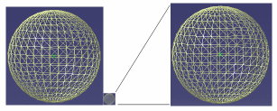 |
|
|
Radius = 100 mm Prop. sag value = 0.20 |
Radius = 10 mm Prop. sag value = 0.20 |
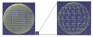 |
|
|
Radius = 100 mm Fixed sag value = 0.20 |
Radius = 10 mm Fixed sag value = 0.20 |
- When working with V4 models, be careful not to set a too high sag value for 3D accuracy, otherwise you will not be able to visualize them.
- As long as the CATPart is not modified (for instance, by creating a point or modifying the pad definition), the 3D accuracy is not taken into account when you save the CATPart using File > Save. However, if you use File > Save As..., the 3D accuracy is taken into account.
- Bear in mind that modifying the value of the 3D accuracy has an impact on the size of your CATPart document. The reason is that a CGR (CATIA Graphical Representation) is stored systematically in the CATPart and the size of this CGR depends on the value you set for the 3D accuracy.
Curves' accuracy ratio
This option lets you control the curve accuracy using the slider
displayed to the right (you can choose a value between 0.1 and 1).
The curve accuracy is a ratio of the 3D accuracy you define using the
above-detailed 3D Accuracy options.
The curve accuracy is calculated as follows:
sag = 3D accuracy x ratio
As a consequence, the tessellation on curves is finer than the tessellation on surfaces.
For instance, setting the 3D sag value to 0.20 and the curve accuracy ratio to 0.10 means that:
- Faces are tessellated with a 0.20 sag
- Curves are tessellated with a 0.02 sag (0.20 x 0.10).
Example 1
Fixed 3D accuracy = 10
Curve accuracy ratio = 1Example 2
Fixed 3D accuracy = 10
Curve accuracy ratio = 0.10
2D Accuracy

Level of Detail

- Static: even if you do not want to move geometry, it is often useful to remove details you do not need to see. Set a low value if you want to see all the details, or a high value to remove details
- While Moving: you can move large parts more quickly if you set this option to a high value. When you release the mouse after moving the part, the normal level of detail is redisplayed.
In both cases, the higher the value, the lower the level of detail. Normally, you set Static to a low value, and While Moving to a high value. The added value is increased display performance.
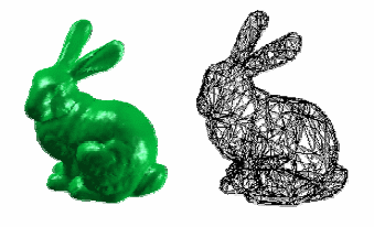
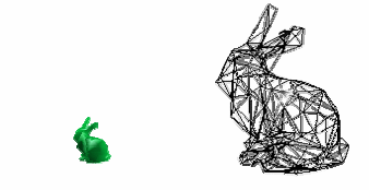
A LOD is an approximation of the mesh intended to reduce the number of polygonal objects in modeling. The purpose of the LOD mechanism is to adjust the polygonal representation of an object to the viewer distance.
You can use the Static and While Moving settings to modify the display quality:
- Static: even if you do not want to move geometry, it is often useful to remove details you do not need to see. Set a low value if you want to see all the details, or a high value to remove details.
Example 1 - The rabbit is near the observer, it occupies a large amount of pixels on the screen and a precise LOD is needed to have a nice rendering: Example 2 - The rabbit is far from the eye, only a few pixels are used on the screen and a rough LOD is enough to render the rabbit:
- While Moving: you can move large parts more quickly if you set this option to a high value. When you release the mouse after moving the part, the normal level of detail is redisplayed.
Below are two examples:
Starting position: While Moving set to default value (3.0): While Moving set to highest value (40.0):
In both cases, the higher the value, the lower the level of detail. Normally, you set Static to a low value, and While Moving to a high value. The added value is increased display performance.
More about LOD (Level of Detail)
- If you are using these options with Product Structure or DMU Navigator functions, you must activate the cache for your LOD settings to be taken into account.
- When working with a model onto which several colors have been applied
(for instance, a different color for each face) using a static or dynamic
level of detail, only one color is displayed for performance reasons.
How is this color selected? The application retrieves the color of all the faces the object is made of and looks for the dominant color (i.e. the most used color). This dominant color is then used for the display.
If you want to see all the colors applied onto the object, set the static or dynamic level of detail to 0.
Pixel Culling

- Static: even if you do not want to move geometry, it is often useful to remove details you do not need to see. To do so, set a high value to remove these details. On the contrary, setting a low value displays the details. For instance, setting 2 means that objects whose size on screen is lower than 2 pixels are static
- While Moving: setting a high value enables you to move large parts more quickly. When you release the mouse after moving the part, the Static size is redisplayed.
Transparency Quality

Low (Screen Door)
Similar to viewing an object through a mesh or a screen. Use this
setting when you need to look at objects through another transparent
object.
This mode is recommended for increased display performance but keep in mind
that only one pixel out of two is rasterized and therefore, some objects
might not be visualized.
When selected, the transparency is not impacted whatever value you set
(between 1 and 255).
 |
 |
| No transparency | Screen Door |
![]() By default, this option is activated.
By default, this option is activated.
High (Alpha Blending)
The produced effect is similar to looking through clear glass. Use this setting when you need to view several transparent objects located at different depths of a scene. For example, looking through a car windscreen at other opaque objects inside the car.
As far as polygons are concerned, the result might not be as expected because in that case, the triangles are blended with the rest of the scene. As it is too costly and may adversely affect performance, polygons are not drawn using a Z order (i.e. depth order) and therefore, it is not possible to be sure that when the transparent polygon is blended, all the scene is drawn behind. Transparent polygons are drawn at the end of the draw phase but they are not depth-stored.
When activated, the transparency is impacted according to the value you
set.
You also need to set the transparency coefficient on selected objects using
Edit > Properties or the Properties contextual
command, by dragging the Transparency slider in the Graphic
tab. Refer to Displaying and
Editing Graphic Properties for more information.
Note that when working in Shading with Material mode:
- the Transparency Quality is automatically switched to High (Alpha Blending)
- if the transparency is set to its maximum value, i.e. 255, then nothing is displayed in geometry area.
This mode is computation-intensive and consequently has an adverse affect on display performance.
 |
 |
| No transparency | Alpha Blending mode |
![]() By default, this option is cleared.
By default, this option is cleared.
Frames per second

Enabled
If this option is selected, it lets you control the minimum number of frames per second (frame rate) during animations (zooming, moving, flying, etc.) when using a regular mouse. The frame rate varies from 1 to 30. Setting a low frame rate keeps a maximum number of details visible, but animations are less smooth and fluid; setting a high frame rate limits visible details, but provides smoother, more fluid animations.
This option is particularly useful, for example, in Fly mode: when flying within large objects, you may not need to see all the details, but you want to navigate through the object in as smooth a manner as possible.
Bear in mind that even though you set the lowest frame rate, there will be a loss of details when this option is selected.
![]() By default, this option is cleared.
By default, this option is cleared.
Frames per second for 3Dx Devices

![]() By default, this option is cleared.
By default, this option is cleared.
Miscellaneous

Show Hidden Edges (whenever possible)
Note that the display of hidden edges is now activated in the View Mode Customization dialog box.
Enable isoparametrics generation
By default, the option is cleared for performance reasons.
To use this option, just follow the steps below:
- Select the Enable isoparametrics generation check box: you are then asked to restart your Version 5 session
- Restart your Version 5 session
- Re-access the Performances tab then, if desired, specify
the number of isoparametrics to be generated for u and v axes using the
Number of isoparametrics in U and V arrows displayed to the
right. You can generate up to 10 isoparametrics. Here, enter
2 - Select View > Render Style > Customize View then select the Isoparametrics check box which is now activated.
The isopamametrics are displayed:
Enable isoparametrics generation
and Isoparametrics are cleared:
no isoparametrics.Enable isoparametrics generation and
Isoparametrics are selected:
2 isoparametrics are displayed for u and v axes
since we entered the value2in step 3.
Enable two side lighting for faces and surfaces only
If this option is selected, it helps you to visualize the two sides (i.e. front side and back side) of a face or surface by lighting them.
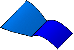 |
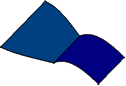 |
| Example with option activated | Example with option cleared |
Enable OpenGL local viewer lighting
If this option is selected, it means that the lighting quality is enhanced by changing the light direction according to the matrix of each vertex. Therefore, each vertex has a better lighting but, depending on the object you are using, creases might appear on the object.
![]() By default, this option is cleared.
By default, this option is cleared.
Save lineic elements in cache
All options related to cgr management are grouped together in the
Cgr Management tab in Tools > Options > Infrastructure > Product
Structure. Therefore, the Save lineic elements in cache
option is not displayed in the Performances tab anymore.
Refer to "Customizing Cgr Settings" in the Version 5 - Product
Structure User's Guide for detailed information.
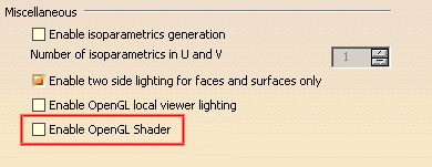
Enable OpenGL Shader
If this option is selected, it lets you apply OpenGL materials when
working with the Real Time Rendering 2 product. These advanced
materials are used to create textures such as paint, wood or marble.
For detailed information, refer to the "Advanced Materials" section in the
Version 5 - Real Time Rendering User's Guide.
To be able to use these advanced materials, you need to download the OpenGL Shader™ development kit. To do so, if you are working on Windows, browse the following Internet site:
http://www.sgi.com/industries/manufacturing/partners/catia/
then send an e-mail to the Strategic Partner Manager (click its name on the page) to ask for the required elements.
The option is displayed when re-accessing the Performances tab:
Enable back face culling

For stand-alone faces
If this option is selected, it avoids redisplay of back sides of faces or surfaces.
Note that when this option is selected along with Enable two side lighting for faces and surfaces only, only front faces are lightened.
![]() By default, this option is cleared.
By default, this option is cleared.
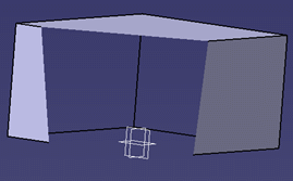
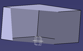
For faces belonging to solids
If this option is selected, it avoids redisplay of back sides of faces or surfaces belonging to solids:
 |
 |
|
Option is selected |
Option is cleared |
- Activating the For faces belonging to solids option has an impact on the Depth Effect... command
- Faces of a solid or of a surface are visualized according to the orientation of the solid's or surface's normal. This enables to know whether a face should be considered as a back face or not and therefore, whether it should be impacted by these options or not
- Clearing these options has an impact on performance because back faces that were not previously drawn are now systematically rendered, whether they can be seen by the user or not.
Halo when displaying the geometry with hidden lines removed

Enabled
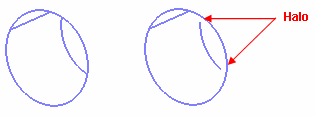
If this option is selected, it lets you display a halo around intersecting edges to create a perspective effect.
Prior to using it, you need to switch to Dynamic hidden line removal mode otherwise, you will not be able to use this option. To do so, select View > Render Style > Customize View then select the Dynamic hidden line removal check box before clicking OK to validate.
The following picture shows an example of halo:
 |
|
|
Example 1 |
Example 2 |
Picking

Window size for picking
Lets you specify the size (in pixels) of the window to be used for
picking elements in normal mode. You can set a value comprised between 1
and 100, the default value being 4 pixels.
The smaller the value, the more precise the picking.
Enable accurate picking
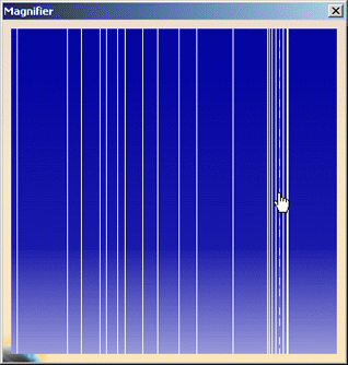
If this option is selected, it helps you select more precisely elements
that are very close to each other when displaying the geometry.
It is recommended to work with a magnified view of your document by
selecting View > Magnifier as shown below:
When the Enable accurate picking check box is selected, the
Window size for accurate picking box is activated to let you
define the size of the window (in pixels) used for accurate picking.
The maximum value you can enter corresponds to the maximum value defined
for the "normal" picking, i.e. the value defined using the Window size
for picking box.
Note that if you this option enables you to use normal picking as well.
The default value is 500 ms but you can increase it up to 2 seconds.
![]() By default, this option is cleared.
By default, this option is cleared.
