In the Geometry tab
![]() select
the geometric components
to be machined.
select
the geometric components
to be machined.
In the Strategy tab
![]() you will find the machining
strategy parameters.
you will find the machining
strategy parameters.
Specify the
tool to be used
![]() (only end mill tools
(only end mill tools
![]() are available for this operation) and speeds and feeds
are available for this operation) and speeds and feeds
![]() .
.
You can also define transition paths in your machining operations by
means of NC macros
![]() as needed.
as needed.
Stiffener: Strategy parameters
Stiffener: Machining Parameters
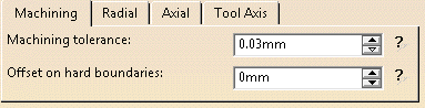
Maximum allowed distance between the theoretical and computed tool path. Consider the value to be the acceptable chord error.
Offset on hard boundaries
Security distance on hard boundaries.
Stiffener: Radial Parameters
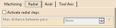
Activate radial steps
When this check box is selected, the tool path includes radial steps.
By default, it is not selected.
Max. distance between pass
Becomes active when Activate radial steps is selected.
Defines the maximum distance between passes.
Stiffener: Axial Parameters
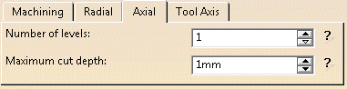
Number of levels
Defines the number of axial parallel passes.
Depth of the cut at each pass.
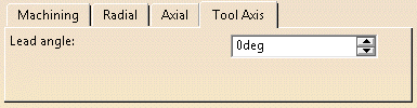
Stiffener: Tool Axis
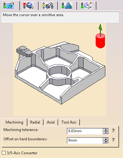
Place the cursor on the vertical arrow and right-click to display the contextual menu.
The item Select opens a dialog box to select the tool axis:
You can choose between selection by Coordinates (X, Y, Z) or by Angles. Angles lets you choose the tool axis by rotation around a main axis. Angle 1 and Angle 2 are used to define the location of the tool axis around the main axis that you select.
- Feature-defined: select a 3D element such as a plane that will serve to automatically define the best tool axis.
- Selection: select a 2D element such as a line or a straight edge that will serve to define the tool axis.
- Manual: enter the coordinates of the tool axis.
- Points in the view: click two points anywhere in the view to define the tool axis.
The Reverse Direction button lets you reverse the direction of the axis with respect to the coordinate system origin.
When available, you can also choose to display the tool and select the position of the tool (default or user-defined).
The item Analyze opens the Geometry Analyser.
Lead angle
Defines the lead angle of the tool axis.
Is available only for the
horizontal part of the stiffener.
Stiffener: Geometry
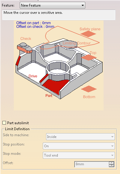
You can specify the following geometry:
- Part with possible offset.
- Check element with possible offset. The check element is often a clamp that holds the part and therefore is not an area to be machined.
- Drive elements, i.e. the stiffeners. They can be selected using the Face Wizard.
-
Safety plane. The safety plane is the plane that the tool will rise to at the end of the tool path in order to avoid collisions with the part. You can also define a new safety plane with the Offset option in the safety plane contextual menu. The new plane will be offset from the original by the distance that you enter in the dialog box along the normal to the safety plane. If the safety plane normal and the tool axis have opposed directions, the direction of the safety plane normal is inverted to ensure that the safety plane is not inside the part to machine.
- Top plane which defines the highest plane that will be machined on the part.
- Bottom plane which defines the lowest plane that will be machined on the part.
- Limiting contour to define the outer machining limit on the part.
Defines what area of the part will be machined with respect to the limiting contour(s). It can either be inside or outside. In the pictures below, there are three limiting contours on the rough stock. The yellow areas will be machined.

Side to machine: Inside
Side to machine: Outside
Specifies where the tool stops:
- Outside stops the tool outside the limit line,
- Inside stops the tool inside the limit line,
- On stops the tool on the limit line.
Offset
Specifies the distance that the tool will be either inside or outside the
limit line depending on the stop mode that you chose.
Stiffener: Tools
End mill tools
![]() and conical tools
and conical tools
![]() are avaialbe for this operation.
are avaialbe for this operation.
Stiffener: Feeds and Speeds
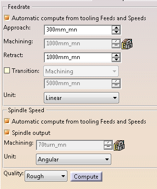
Feedrates and spindle speed can be defined in linear or angular units.
A Spindle output check box is available for managing output of the SPINDL instruction in the generated NC data file. If the check box is selected, the instruction is generated. Otherwise, it is not generated.
Feeds and speeds of the operation can be updated automatically according to tooling data and the Rough or Finish quality of the operation. This is described in Update of Feeds and Speeds on Machining Operation.
Stiffener: Macro data
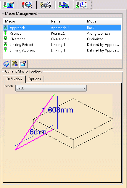
For more information on how to save or load an existing macro, please refer to Build and use a macros catalog.