Refer to Stiffener in the Reference section for more details about this operation.
-
Open SampleAMG.CATPart from the samples directory.
-
Select the Stiffener
 icon
and select Machining Program.1 in the specification tree.
icon
and select Machining Program.1 in the specification tree.
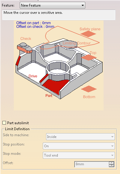
The dialog box opens at the geometry tab page .
.
This page includes a sensitive icon to help you specify the geometry to be machined.
The area that represents the part geometry is colored red indicating that the geometry is required
for defining the area to machine. All of the other geometry parameters are optional.
-
Click the red area in the sensitive icon and select the part in the viewer.
Then double-click anywhere in the viewer to confirm your selection and redisplay the dialog box. -
Click Bottom, and select the corresponding geometry.
You must select the bottom of the part before searching the stiffeners, especially in symmetric parts:
The faces under the bottom plane are then ignored. -
Go to the Strategy tab
 and define the
tool axis.
and define the
tool axis.
As stifferners are searched for in the part, with respect to the tool axis, you need to define both before starting the selection of the stiffeners. -
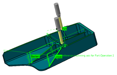
Back in the Geometry tab, click the red area representing the Drive.
In the Face Selection toolbar, select Stiffener Selection .
.
Automatic detection of the stiffeners selects most stiffeners. You need to select the rest manually.
-
In the Stiffeners Selection dialog box:
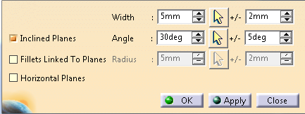
- Define the Width of the stiffeners, with a possible +/- tolerance.
- Define the domain of the search by selecting the
corresponding check boxes:
- Horizontal Planes. Requires no other input.
- Inclined Planes. You must enter the value of the Slope, with a possible +/- tolerance.
- Fillets linked to planes. You must enter the Radius, with a possible +/- tolerance.
- Retrieve existing Slope, Width or Radius value:
- Click
 on the right of the required value.
 - Pick the corresponding area on the part.
The value is retrieved and the dialog box is updated.
- Click
- Click Apply.
The faces corresponding to the criteria are added to the selection. - Repeat with other values as needed to complete the selection and click OK.
-
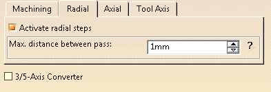
Back in the machining operation dialog box, go to the Radial tab and select the Activate radial steps check box to create radial passes along the inclined stiffeners. They are created only if a single pass is not sufficient to remove all the material.
-
Go to the Tools tab
 to select a
tool.
to select a
tool.
For most cases, use a milling cutter with a radius to work from bottom to top
and a large milling cutter to ensure a good quality of planes
-
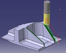
Click Tool Path Replay
 to check the validity of the Machining Operation.
- The tool path is computed.
- A progress indicator is displayed.
- You can cancel the tool path computation at any moment before 100% completion.
- The tool path is computed.
![]()