You can modify this tool in several ways:
- edit its characteristics, thereby creating a new tool
- replace it by selecting another tool that is already used in the document
- replace it by selecting another tool by means of a query.
If you want to change tool type, select the icon corresponding to the desired tool type. In this case the corresponding tool representation appears in the 2D viewer.
- Double-click the geometric parameter that you want to modify in the 2D viewer, then enter the desired value in the Edit Parameters dialog box that appears. Modify other parameters in the same way. The tool representation is updated to take the new values into account.
- Click More to expand the dialog box to access all the tool's parameters.
Modify the values as desired. - Use the spinner to increment the Tool number.
- Enter a name for the new tool.
- Select the button opposite Name.
- Select the desired tool from the list of tools already used in your document.
- The tool representation is displayed in the 2D viewer. It can be edited as described above.
- Click the Select a tool with query icon opposite Name. The Search Tool dialog box appears.
- In the Look in list, specify where you want to search
for the tool:
- in the current document
- in a tool catalog
- in an external tool database such as the TDM (Tool Data Management) or CATIA Version 4 Manufacturing database.
- If you want to change tool type, select the icon corresponding to the desired tool.
- You can do a quick search in the Simple tab page by means of a character string on the tool name or a value for the tool's nominal diameter. The tools meeting the simple search criteria are listed.
- Select the desired tool from the list and click OK.
The tool representation is displayed in the 2D viewer. It can be edited as described above.
- You can search a tool using finer constraints by selecting the
Advanced tab page.
The example below shows the result of a search for a tool with body diameter between 8mm and 12mm in the catalog ToolsSample02.
- Click Select a tool with query icon opposite Name. The Search Tool dialog box appears.
- Select All Tools.
All tools under the applicable tool types are displayed in the tools list (in this above example, all face mill, end mill, T-slotter tools are displayed). The table shows all the attributes of all possible types.
- Click Advanced tab. Define a
tool query using attributes that are common to the applicable tool
types.
- if the tool number of the new tool already exists in the Resource List
- if the new tool does not exist in the Resource List.
Cutting conditions (feeds and speeds) can be included in a tool catalog and in the TDM. Please refer to Feeds and Speeds for more information.
The TDM can allow several cutting speed and feedrate data for each tool. This information is displayed at tool selection time.
The feed and speed information of the selected tool is used in the machining operation definition.
Realistic DXF user representation of tools can be selected from the TDB. These can be used in tool path replay as well as Photo and Video simulations.
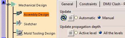
NOTE: Update propagation depth within Tools
> Options > Mechanical Design > Assembly Design > General tab needs to be selected as All the Levels and not as Active Level so that the tool product is up-to-date. Otherwise
the selection of Active Level results in the tool becoming not up-to-date and eventually the tool path gets deleted after clicking OK in
the Manufacturing Operation dialog box. Hence in order to avoid this problem select All the Levels for Update propagation depth.
![]()