Creating a Tetrahedral Mesh for 3D Bolt Models
The objectives of the tetrahedral meshing procedure for 3D bolts are to create a planar section of element faces across the bolt shaft and a complete mesh that is suitable for analysis. The pretension cutting plane must coincide with the planar section of element faces to ensure that the bolt pretensioning tool will work. Nonplanar element faces at the cutting plane may cause an error during the analysis.
The following is the recommended procedure to mesh 3D bolts. Other procedures may or may not produce acceptable results.
Prior to meshing, you must create an intersection plane and a boundary edge on the bolt shaft at the desired pretension location:
In the Wireframe and Surface Design workbench, create a plane on the bolt shaft at the desired pretension location.
Select the Intersection
 tool.
tool.Pick the plane on the bolt shaft as as the First Element and the bolt shaft as the Second Element to define an intersection plane.
Use the Boundary
 tool, and select the intersection plane defined in the previous step as the Surface Edge to define a boundary edge on the bolt shaft where it crosses the plane.
Enter the Advanced Meshing workbench.
Select the Advanced Surface Mesher
 tool.
tool.Select the PartBody of the bolt as the geometry to be meshed.
In the Global Parameters dialog box, choose appropriate parameters for the size of the bolt.
Click OK to close the Global Parameters dialog box.
Use the Add/Remove Constraints
 tool to add the boundary edge curve created in Step 1 (Boundary.1/surfs/PartBody) as a constraint for the surface mesh.
Click OK to close the Add/Remove Constraints dialog box.
Mesh the part.
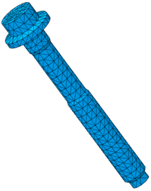
CATIA V5 creates Advanced Surface Mesh.1 on the bolt surface.
Exit the current procedure.
Select the Advanced Surface Mesher
tool again.Select the intersection plane surface created in Step 1 (Intersect.2/surfs/PartBody).
Toggle on Automatic mesh capture and set an appropriate tolerance
Use the Mesh Part Selector
 to select Advanced Surface Mesh.1, created in Step 9.
Automatic mesh capture ensures that nodes on the perimeter of the intersection plane are shared between both surface meshes.
Mesh the part.
CATIA V5 creates Advanced Surface Mesh.2 on the intersection plane.
Exit the current procedure.
Select the Tetrahedron Filler
 tool.
tool. In the Tetrahedron Filler dialog box, select both surface meshes (Advanced Surface Mesh.1 and Advanced Surface Mesh.2) as the MeshParts.
Click OK to continue.
Deactivate Advanced Surface Mesh.1 and Advanced Surface Mesh.2 in the specification tree.
The surface meshes were needed only to create the tetrahedral filler mesh on the bolt.
Update all meshes.