Defining Pretensioned Bolts in a Model
Creating pretensioned bolts is more complex than using bolt tightening or rigid bolt tightening connection properties, but the resulting bolts are modeled more accurately. Pretensioned bolts have the following advantages:
bolt loads can be applied at any analysis step;
bolts are modeled as parts using flexible beam or 3D elements, including material property assignments; and
bolts are applied to only the analysis cases and steps in which they are defined.
Figure 8–10 shows two parts fastened with a pretensioned bolt. The right-hand image shows the bolt pretension property (modeled using beam elements) and the rigid coupling connection meshes used to attach the bolt ends to the assembly.
If you create three-dimensional bolt models, you can choose from several methods to attach the bolt to the rest of the assembly, such as contact pairs and fastened pairs. For three-dimensional bolts, you must define a cutting plane through the bolts on which the pretensioning loads will be applied.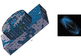
This task shows you how to create pretensioned bolts in a model.
Create or open the assembly model to which you want to add bolts.
Model each bolt using either:
one-dimensional geometry (lines), or
three-dimensional geometry.
Apply a material to the bolt geometries.
Mesh the bolts as appropriate for the geometry chosen in Step 2:
Use beam elements for one-dimensional geometry; each bolt must have at least three beam elements along its length.
Use three-dimensional elements for three-dimensional bolt geometry—tetrahedral or hexahedral elements will facilitate creation of a planar mesh surface to be used as the cutting plane required for a 3D bolt pretension property. See Creating a Tetrahedral Mesh for 3D Bolt Models, or Creating a Hexahedral Mesh for 3D Bolt Models for details.
Select Start>Analysis & Simulation>Nonlinear Structural Analysis from the menu bar to enter the Nonlinear Structural Analysis workbench. If necessary, set an empty Nonlinear Structural case to be the current case.
Use rigid or smooth couplings or other modeling techniques to connect the bolt ends to the parts being bolted together.
Apply a 1D property or 3D property to the geometry or mesh of each bolt, as appropriate for the geometry and mesh used in the previous steps.
Create a bolt pretension property using the bolt geometry as the support. You must also select a cutting plane for use with 3D bolts. See Creating a Bolt Pretension Property for details.
Create the desired analysis steps.
Complete one of the following to tighten the bolt:
Pretension
Create a point load (see Creating Point Loads) for each bolt in the step where you want to apply the bolt load, and select the bolt pretension property as the support. In a subsequent step, create a displacement boundary condition (see Creating Displacement Boundary Conditions) using the bolt pretension property as the support. Use the Fix at current position option to maintain the initial adjustment of the pretension section. The bolt force can then change as the model responds to other loads.
Set length
Create a displacement boundary condition to tighten the bolt by a specified length; select the bolt pretension property as the support.
Note: You can select multiple bolt pretension properties as the supports for either the point load or the displacement boundary condition to apply the same load to all of the bolts.