Creating Fastened Pairs
A fastened pair is the link between two part bodies that are tied together at their common boundary and behave as if they were a single body. From a finite element model point of view, this is equivalent to the situation where the corresponding nodes of two compatible meshes are merged together. However, since part bodies can be meshed independently, fastened pairs are designed to handle incompatible meshes.
Fastened pairs take into account the elastic deformability of the interfaces.
You can use a general analysis connection or a Contact or Coincidence assembly constraint to define the surfaces that are interacting. For more information, see Specifying Contact Surfaces. Table 6–2 summarizes the constraints and connections that can be used to define a fastened pair in Abaqus for CATIA V5.
| Assembly Design Workbench | Abaqus for CATIA V5 | |
|---|---|---|
| Coincidence Constraint | Contact Constraint | General Analysis Connection |
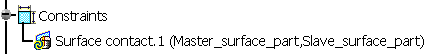
The order in which the two surfaces are specified when the constraint or connection is defined is critical because of the manner in which their interaction is discretized. The first surface selected is considered the “master” surface, and the second surface selected is considered the “slave” surface. When a constraint is added to the specification tree, the surfaces are listed in this order, as shown in Figure 6–7.
Figure 6–7 The specification tree entry for a Contact assembly constraint, showing the master and slave surfaces.
For each node on the “slave” surface Abaqus attempts to find the closest point on the “master” surface of the contact pair where the master surface's normal passes through the node on the slave surface. The fastened pair is then discretized between the point on the master surface and the slave node.
A fastened pair does not necessarily fasten the entire selected slave surface to the master surface. Instead, Abaqus for CATIA V5 uses a position tolerance, or distance from the master surface, to determine which nodes on the slave surface should be fastened to the master surface; any slave nodes outside of this tolerance in the initial model configuration are not included in the fastened pair. Abaqus calculates a default position tolerance based on a number of factors in the model. This default tolerance is typically suitable for fastening two proximate surfaces, but you can redefine the position tolerance if necessary.
If you need to create multiple fastened pairs in a model, you should consider using the interaction wizard. The interaction wizard automates many of the steps involved in defining fastened pairs and can create multiple fastened pairs simultaneously. See Using the Interaction Wizard for more information.
This task shows you how to create a fastened pair between two parts.
Click the Fastened Pair Property icon
 .
.The Fastened Pair dialog box appears, and a Fastened Pair object appears in the specification tree under the Properties objects set.
You can change the identifier of the fastened pair by editing the Name field.
In the specification tree, select a general analysis connection or a Contact or Coincidence assembly positioning constraint to apply to the fastened pair.
The Supports field is updated to reflect your selection. The first surface specified in the connection or constraint is used as the master surface in the contact pair; the second surface is used as the slave surface.
Optionally, if either or both of the surfaces involved in the fastened pair are shells, click Flip Master and/or Flip Slave to reverse the direction of the surface normals.
To reverse the order of the master and slave surfaces in the fastened pair definition, toggle on Swap master and slave surfaces.
The red highlighting and arrows indicating the master surface replace the green highlighting and arrows indicating the slave surface, and vice versa.
To help you view the configuration of the master and slave surfaces in a complex model, you can use the Visibility Options to view only the part containing the master surface or only the part containing the slave surface.
If you are using the fastened pair to define the connecting boundaries in a cyclically symmetric model, toggle on Enable Cyclic Symmetry. Cyclic symmetry cannot be defined in Explicit Dynamics cases. See Using Cyclic Symmetry in a Model for details.
Select the appropriate Position Tolerance for the fastened pair:
Choose Use computed default to use the position tolerance that is calculated automatically by Abaqus. For more information about how Abaqus calculates the position tolerance, see Mesh tie constraints in the Abaqus Constraints Guide.
To define the position tolerance directly, choose Specify distance, and enter a position tolerance.
If you define the position tolerance directly, you can preview which slave nodes are included in the fastened pair by clicking Highlight nodes; Abaqus for CATIA V5 highlights those nodes on the slave surface that lie within the specified position tolerance from the master surface. Both surfaces involved in the fastened pair must be meshed to preview the fastened nodes. The previewed nodes are approximations only; the nodes indicated in the preview display may be slightly different than the nodes that are fastened during the analysis. However, the preview should identify general regions of interest in the model when configuring a fastened pair.
By default, Abaqus moves all slave nodes in a fastened pair directly onto the master surface at the beginning of an analysis. This adjustment does not create strains in the model and typically improves performance. To allow initial gaps between the fastened surfaces to remain during the analysis, toggle off Adjust slave node initial position.
Select the Formulation option for the fastened pair:
Select Solver Default to use the best formulation as determined by Abaqus.
Select Node to Surface to use the node-to-surface formulation.
Select Surface to Surface to use the surface-to-surface formulation.
If you are not using the Solver Default formulation, you can ignore the thickness associated with shell elements in the fastened pair by toggling off Include shell element thickness.
Click OK in the Fastened Pair dialog box.
A symbol representing the fastened pair appears on the corresponding faces.