For defining the built-in slot, you have to:
|
These steps apply to Ship Structure Detail Design application. |
Create a Slot Reference
-
Click Start > Mechanical > Part Design.
The New Part dialog box appears. -
In the Enter part name box, enter the slot name and click OK.
The nomenclature for slot is <SlotType>_<ProfileType>. Here we named it as RECT_Tee.The RECT_Tee.CATPart is created. -
Under the geometrical set, define the parameters and formulas.
- Click Tools > Formulas to define the parameters and formulas.
- Create parameters.
For more information about creating parameters, refer to CATIA Infrastructure User's Guide: Using Knowledgeware Capabilities: Parameters. - Differentiate them using prefix Priv_ and Pub_
respectively.
The parameters are created in the tree below the Parameters node.
Only public parameters are visible while instantiating a slot. - Create formulas using the private and public
parameters.
The formulas are defined to relate private parameters with public parameter values. These formulas are defined by the administrator.
For more information about creating parameters, refer to CATIA Infrastructure User's Guide: Using Knowledgeware Capabilities: Relations: Formulas.
The parameters and formulas are defined.
-
Create a design table:
- Create an excel file or modify the excel file
sample.
Here we referred RECT_Tee.xls.
This sample file is provided with the application. It is located in the following folder:
.../OS/startup/EquipmentAndSystems/Structure/DetailingFeatures. - In the excel file, enter the part number in the
PartNumber column.
The part number should be named as <SlotType>_<ProfileType>_<SectionName>.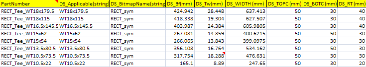
- Create a design table which defines values for all types
of sections for a given family using the excel file.
Here we created the design table for family Tee.
For more information about design table, refer to CATIA Infrastructure User's Guide: Using Knowledgeware Capabilities: Relations: Design Tables. - Associate the design table with the respective part with
the help of part number.
The design table is added under the Relations node in the specification tree.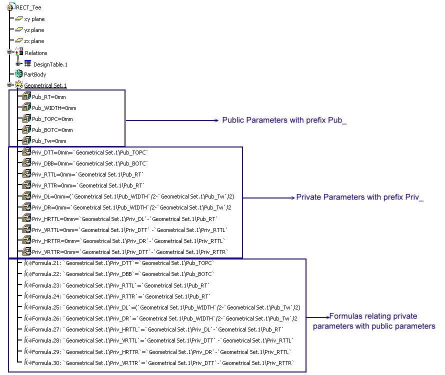
The public parameters are listed in the design table.
- Create an excel file or modify the excel file
sample.
-
Create a power copy:
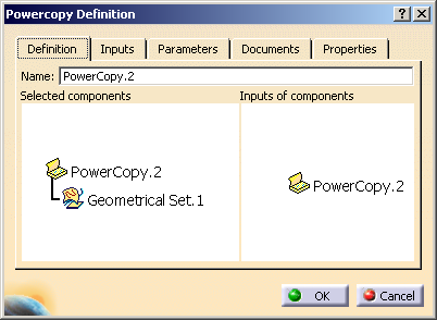
- Click Insert > Knowledge Templates > Power Copy.
The Powercopy Definition dialog box appears. - Select the geometrical set in the specification tree.
- Select the Parameters tab.
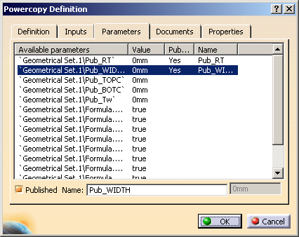
- Select the parameter which you want to publish.
- Select the Published Name check box and edit the parameter name by adding Pub_ as prefix.
- Click OK.
The power copy is created.
- Click Insert > Knowledge Templates > Power Copy.
-
Click File > Save to save the slot reference.
The slot reference is created and saved.
Add Slots to a Catalog
.../OS/startup/EquipmentAndSystems/Structure/DetailingFeatures
You also need to modify Chapter and Family information. For more information, refer to Using the Structure Detailing Features Catalog.
-
Click Start > Infrastructure > Catalog Editor.
You entered the Catalog Editor workbench. -
Open the existing catalog: StructureDetailingFeatures.catalog.
The catalog editor opens showing the contents of the sample catalog. 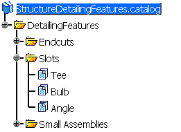
Every slot type should be associated with each profile type. There exist 12 combination: - RECT_Tee, RECT_Bulb, RECT_Angle
- BOOT_Tee, BOOT_Bulb, BOOT_Angle
- BULB_Tee, BULB_Bulb, BULB_Angle
- FLAR_Tee, FLAR_Bulb, FLAR_Angle
-
Activate the Tee node.
-
Click Add Generative Part
 in the Data toolbar.
The Part Family Definition dialog box appears. -
Click Select Document.
Select the required CATPart. The path of the selected part is displayed in the File Name box. -
Click OK.
In the Reference tab, for every configuration of the design table, a part family configuration is created.
In the Keyword tab, all the public parameters along with their values are listed. -
Click File > Save to save the part in the catalog.