|
The slot built-in geometry is a specific feature computing a contour
for an opening to allow the profile to pass through a plate or another
profile. It is defined by a curve produced by a set of parameters and
faces extracted from the profile, with some conventions.
The following topics provide a detailed information about slot
parameters:
|
|
|
Slot Parameters
|
|
|
One or more than one parameters define a straight line or a circle.
The intersection of straight lines and circles are connected in a
predefined sequence to generate a contour.
- Auxiliary parameters are the parameters which cannot
exist alone. They are always interpreted with some other parameters.
- Collaborative parameters are the parameters which exist
in a set. The absence of even one parameter from the set
affects the other parameters and makes them meaningless.
|
|
|
|
Parameters Defining a Straight Line or Distance
|
|
|
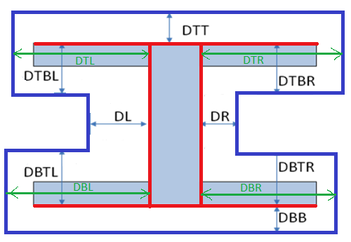
The name of straight linear parameters starts with letter D
(distance).
There are 12 parameters that define straight lines with respect to
horizontal (H) or vertical (V) linear dimensions of an I-section for
example.
The four faces (highlighted in red color) are used to calculate the
distances.
- Five of these twelve parameters are related to top
flange (MoldedFlange2): DTT, DTR, DTBR, DTBL (symmetry of
DTBR/V), DTL (symmetry of DTR/V).
- Five of these twelve parameters are related to the
linear dimensions of bottom flange (MoldedFlange1): DBTR
(symmetry of DTBR/H), DBTL (symmetry of DTBL/H or symmetry
DBTR/V), DBL (symmetry of DBR/V or symmetry DTL/H), DBB
(symmetry of DTT/H), DBR (symmetry of DTR/H).
- Two of these parameters define lines on both sides of
web (WebInner+ and WebInner-): DR, DL (symmetry of DR/V).
|
|
|
|
Parameters Defining a Circle
|
|
|
A radius parameter exists only with two additional parameters that
define the center for the circle. Thus, a circle defining parameters
exists in a group of three and constitutes a set of collaborative
parameters.
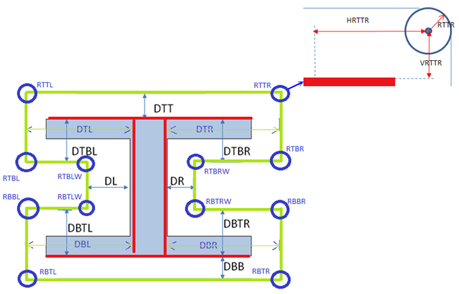
The name of radius parameters starts with letter R (radius). The
parameters defining center coordinates start with H (if it defines
horizontal coordinate) or with V (if it defines vertical coordinate)
followed by the name of radius.
There is one radius parameter corresponding to each corner. Twelve
circles (hence arcs) can be defined using 36 parameters.
- At top flange:
| RTTR |
HRTTR |
VRTTR |
| RTTL |
HRTTL |
VRTTL |
| RTBL |
HRTBL |
VRTBL |
| RTBLW |
HRTBLW |
VRTBLW |
| RTBRW |
HRTBRW |
VRTBRW |
| RTBR |
HRTBR |
VRBTR |
- At bottom flange:
| RBTLW |
HRBTLW |
VRBTLW |
| RBTL |
HRBTL |
VRBTL |
| RBBL |
HRBBL |
VRBBL |
| RBBR |
HRBBR |
VRBBR |
| RBTR |
HRBTR |
VRBTR |
| RBTRW |
HRBTRW |
VRBTRW |
|
|
|
|
 |
When using circle parameters, you need to know
the face from which the horizontal and vertical coordinates are
computed. For example, RTBR is located at right of face right, and below
the top face. That means the coordinates are computed positively from
these two references. If you want to locate RTBR above top face, then
you should use negative value for the vertical coordinates. |
|
|
|
Straight Lines at an Angle to Section Linear Elements
|
|
|
An auxiliary angle parameter along with one of
the parameter is used to create a slant line. The names of auxiliary
angle parameters start with A. There is a one-to-one correspondence
between parameters of distance and these auxiliary parameters. Thus,
there are twelve angle parameters corresponding to each linear
parameters defined above.
- Angle parameter for top flange offset distance: ADTT
ADTR ADTBR ADTBL ADTL.
- Angle parameter for bottom flange offset distance: ADBTR
ADBTL ADBL ADBB ADBR.
- Angle parameter for both sides of web: ADR ADL.
|
|
|
|
|
|
The angle is measured in:
- Counterclockwise for all right vertical lines and all
horizontal lines.
- Clockwise for all left vertical lines.
|
|
|
|
|
Snipe Straight Lines
|
|
|
There are two offset linear parameters corresponding to each corner.
These parameters always exist in pair. A pair defines a snip at a
corner. If a pair of parameters is defined at a corner, a radius
parameter cannot be defined at the same corner and vice versa.
One trim parameters defines end of a line defined by an offset
parameter.
|
|
|
Super Curve of Parameters
|
|
|
The curve is computed from the parameters,
proceeding with an anti-clockwise direction. All the above parameters
(also called private parameters) used to build the contour are created
in a reference slot object.
It is possible to make the contour parametric to maintain continuity and
to ensure symmetry by adding new parameters to drive the others. This
method requires formulas between the private parameters, and also adds
new parameters, named public parameters. Those formulas are added in the
slot reference.
|
|
|
About Slot Type and Profile Type
|
|
|
|
|
|
In the catalog, there are three profile types:
|
Here we are considering four slot types. There can be 'n'
number of possibilities of slot type.
|
Every slot type should be associated with each profile type. There exist
12 combination:
- RECT_Tee, RECT_Bulb, RECT_Angle
- BOOT_Tee, BOOT_Bulb, BOOT_Angle
- BULB_Tee, BULB_Bulb, BULB_Angle
- FLAR_Tee, FLAR_Bulb, FLAR_Angle
|
For each combination, you can create a reference .CATPart and each part
will have formulas to define relationship between private and public
parameters. |
|
 |