Top surfaces extend the stamped part, and are continuous either directly with the part or with the clean contour surfaces.
They are referred to as Reference Surface.
-
Select an axis system (stamping direction) and the surface to extend.
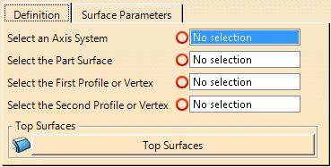
When you select the part surface, its boundary is analyzed, and tangency discontinuities are displayed. -
Select the first profile or vertex used to create the top surface.
Use the contextual toolbar on the selection to create or edit profiles.
See Creating Profiles for more information. -
Select the second profile or vertex used to create the top surface.
- It must be of the same type as the first one (Select two profiles or two vertices).
- You cannot select an element already selected as first profile or vertex and vice-versa.
- If you have selected two vertices, you can create or edit top surfaces, with or without fillets, from the contextual toolbar.
- If you have selected profiles, you can create or edit profiles or addendum surfaces from the contextual toolbar.
- Profiles can be rotated along the Y-direction, in the UW plane.
- The Z-direction of a profile can be aligned with the Z-direction of the input axis system.
-
Select an opening line (Intersection of the wall surfaces and the binder).
-
Click Top Surface
 to create one.
An Addenda Surface Set is created.
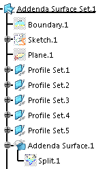
Profiles are created on the selected section, one on each
tangent discontinuity.
A multi-section surface is then
created between the profiles.
Whenever possible, one surface
is created between two profiles.
Il not possibe, several
surfaces are created.
![]()