-
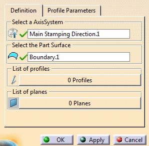
Select a vertex.
The Compass snaps to the selection.
A contextual toolbar appears.
The dialog box lists are updated.
Multi-selection of profiles is available. Drag the compass to set the length or orient the profile.
-
Alternatively, in the contextual toolbar define the direction:
-
 Switches between X-Axis and Y-Axis directions.
 -
 Aligns the selected profiles in the X-Axis direction.
 -
 Aligns the selected profiles in the Y-Axis direction.
 -
 Makes the profile perpendicular to the stamping direction.
 -
 Creates or removes a tangency constraint with the selected
surface.
Creates or removes a tangency constraint with the selected
surface.
-
-
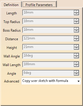
Still in the contextual toolbar:
-
Click OK.
The profile is created under a Profile Set.
![]()