Design changes are supported.
-
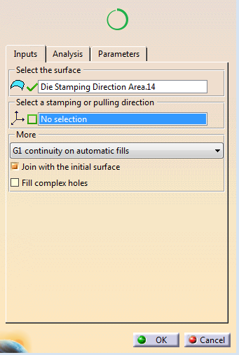
Select an axis system (Pulling or stamping direction).
Selecting an axis system is mandatory to compute draft patches, optional otherwise.
Draft patches are an option to fill complicated holes.
However, huge discontinuities in the wire that defines the hole can lead to a twisted result. -
The percentage circle indicates the percentage of holes that are filled.
Partially orange when not all holes are filled, green when all holes are filled. -
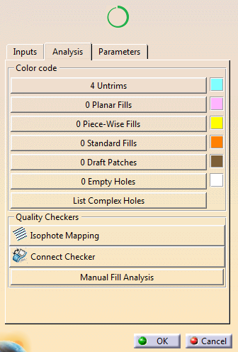
- Filled holes
are listed by category, with their numbers and colors.
Press a category to access the list.
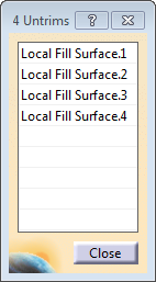
- Select a hole in the list. Use the user actions in the contextual toolbar
- Use Isophote Mapping to display discontinuities between faces.
- Press Connect Checker to analyze tangency between faces.
- Press Manual Fill Analysis
to check that
continuity requests are met for holes filled by an user
action.
User actions can be:- Remove the filling.
- G0, G1, or G2 Fill.
- Piece-Wise Fill (With G0, G1, or G2 constraints and G0, G1, G2 Connect Curve).
- Fill by Draft Patch, with parameters proposed in the contextual toolbar.
-
 Reframe on the selection
 -
 Delete the filling of a specific hole
 -
 Create a draft patch on a specific hole
 -
 Create a fill on a selected hole
 -
 Create a Piece-Wise fill on the selected hole
 -
 Set a G0 continuity
 -
 Set a G1 continuity
 -
 Set a G2 continuity
 -
 Set a G0continuity on connect curves
 -
 Set a G1 continuity on connect curves
 -
 Set a G2 continuity on connect curves.
- Filled holes
are listed by category, with their numbers and colors.
-
Back in the Inputs tab, under More
- Select a G0, G1 or G2 continuity on automatic fills.
Note that a Piece-Wise fill with a G2 continuity may fail when processing two bounded faces supported by trimmed surfaces with a large empty area. - Decide to join the initial surface to the result fillings.
- Opt to fill complex holes.
This option provides more results but requires that you check them as quality is not guaranteed.
- Select a G0, G1 or G2 continuity on automatic fills.
-
If you have selected Fill complex holes, press List Complex Holes in the Analysis tab.
- Select one hole in the list to inspect it.
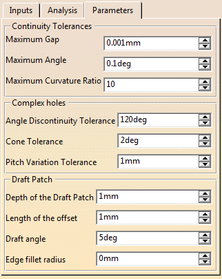
- Set required parameters.
![]()